Compaction direction is a structural design parameter, not merely a manufacturing detail. Compression-molded and sintered PTFE billets retain microstructural anisotropy from the original pressing operation, so their fracture behavior depends on orientation. For custom CNC-machined components under mechanical stress, the part should generally be oriented so its primary stress vectors run parallel to the billet’s original compaction axis, improving fracture stability and reducing the risk of sudden cleavage.
The CNC machining process shapes the PTFE but does not eliminate its internal directional structure. Identify the billet’s compaction axis, then orient the component so its dominant mechanical loads are parallel to that axis—especially in pressure vessels, flange adapters, and valve housings.
Why PTFE Retains Directional Behavior
Compression creates an anisotropic microstructure
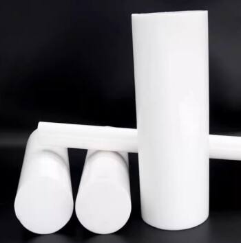
During compression molding, PTFE powder is compacted along a specific pressing direction before sintering. This process produces a billet whose internal structure and potential defect paths are not mechanically identical in every direction.
As a result, a machined part made from the billet can have different crack-growth behavior depending on how it is cut and loaded.
Machining does not reset the material orientation
CNC machining changes the component’s geometry, but it does not homogenize the billet’s microstructure. A cylindrical housing, flange, or adapter therefore inherits the billet’s original directional behavior.
The relevant orientation is the billet compaction axis, not simply the direction of the CNC toolpath or the visible grain of the finished surface.
How Compaction Direction Affects Fracture
Crack growth is more stable in one orientation
Experimental evaluations indicate that crack propagation perpendicular to the billet pressing direction is substantially less stable than crack growth parallel to the pressing direction.
Less stable crack growth is important because a crack can extend abruptly rather than progressing in a controlled manner. In a mechanically loaded PTFE component, that can produce sudden structural cleavage with limited warning.
Stress orientation influences failure risk
The primary design objective is to align the component’s dominant mechanical stress vectors parallel to the original compaction axis. This orientation supports more stable fracture behavior under the loading conditions described in the reference material.
This is particularly important when the component is exposed to sustained pressure, concentrated clamping forces, bending, or loads that can initiate cracks at corners, bores, threads, or sealing interfaces.
Where Orientation Matters Most
High-pressure vessel bodies
Pressure-containing PTFE bodies should be oriented with their principal mechanical loading parallel to the billet compaction direction wherever the geometry and manufacturing route permit.
The design should also avoid unnecessary stress concentrations, because a favorable material orientation cannot compensate for a sharp internal corner, thin wall, or poorly supported sealing region.
Flange adapters
Flange adapters commonly experience bolt preload, sealing compression, and pressure-induced forces simultaneously. Their orientation should be evaluated against the actual load path rather than selected solely for material efficiency or ease of machining.
The billet axis should be documented before machining so the finished adapter can be positioned intentionally within the billet.
Valve housings
Valve housings may experience pressure cycling, localized clamping, actuator loads, and vibration. These combined forces make directional fracture behavior more consequential than it would be in a lightly loaded static spacer.
For complex housings, map the dominant stress vectors first, then select the billet orientation and machining layout around that load map.
Designing Around the Billet Axis
Confirm the billet’s pressing direction
The supplier or material documentation should identify the billet’s compaction direction. If that information is unavailable, the orientation should not be assumed from the finished part’s appearance.
For safety-critical or highly loaded components, obtain traceable material information and discuss the intended machining orientation with the PTFE manufacturer or qualified materials engineer.
Map the actual load path
Do not rely only on the nominal pressure rating. Consider how pressure, bolt preload, bending, impact, vibration, and thermal or assembly loads combine in the finished component.
The most important direction is the direction of the dominant mechanical stress, particularly around holes, threads, shoulders, sealing grooves, and transitions in wall thickness.
Preserve adequate supporting material
Orientation works together with geometry. Maintain sufficient wall thickness, use appropriate radii at transitions, and avoid placing critical features where the material is forced to carry highly concentrated loads across an unfavorable direction.
The goal is to prevent a local defect from becoming an unstable crack path.
Dynamic and Repeated Loading
Vibration can increase the importance of orientation
Movement and vibration introduce repeated or changing stresses rather than a single static load. Even when each individual load is moderate, cyclic loading can repeatedly challenge the same local features.
For dynamic applications, evaluate the stress direction throughout the operating cycle, not just at one stationary position.
Packing applications require a separate material decision
If the requirement concerns moving seals or packing rather than a rigid machined pressure component, a machined PTFE body may not be the best solution. PTFE braided packing or PTFE chevron packing can be more suitable where movement, vibration, and sealing compliance are central requirements.
The correct choice depends on whether the component must function primarily as a rigid structural body or as a dynamic sealing element.
Understanding the Trade-offs
The ideal orientation may conflict with billet utilization
Orienting the component correctly may increase scrap, require a larger billet, or constrain the machining layout. Those costs are real, but they should be weighed against the consequences of unstable fracture in a mechanically stressed part.
Material savings should not automatically override the load-direction requirement.
Orientation is not a complete design qualification
Aligning stress vectors with the compaction axis improves the fracture-stability design basis, but it does not guarantee structural performance. Pressure level, geometry, temperature, chemical exposure, creep, tolerances, and installation loads must also be assessed.
Highly loaded or safety-critical parts may require representative testing or engineering validation.
Do not confuse orientation with strength in every direction
The compaction direction should be treated as a fracture-behavior consideration, not a universal promise that PTFE is stronger along one axis under every possible loading mode.
The final design must be evaluated using the relevant failure mode: tensile stress, compression, bending, shear, pressure cycling, or crack initiation at a feature.
How to Apply This to Your Project
Use the following workflow before releasing a custom CNC-machined PTFE component for production:
- If your primary focus is pressure containment: Identify the billet compaction axis and orient the vessel, adapter, or housing so its dominant stress vectors run parallel to that axis.
- If your primary focus is dynamic sealing: Evaluate PTFE braided or chevron packing instead of assuming a rigid machined component is the best solution for movement and vibration.
- If your primary focus is manufacturing efficiency: Compare billet utilization against the consequences of using an unfavorable orientation, including unstable crack growth and potential sudden cleavage.
- If your primary focus is safety-critical performance: Obtain documented billet orientation, perform a full load-path review, and validate the final geometry and material orientation through appropriate engineering analysis or testing.
Treating compaction direction as part of the component specification lets you use CNC machining to shape PTFE without overlooking the material structure that governs how it may fail.
Summary Table:
| Factor | Recommendation |
|---|---|
| Compaction Axis | Identify billet pressing direction from supplier documentation |
| Stress Orientation | Align dominant mechanical stresses parallel to compaction axis |
| Crack Growth | Parallel orientation yields more stable crack propagation |
| High-Risk Components | Pressure vessels, flange adapters, valve housings require load-path mapping |
| Dynamic Loading | Evaluate cyclic stresses; consider PTFE braided/chevron packing for sealing |
| Design Trade-offs | Balance material utilization vs. fracture risk; orientation is not a substitute for full design qualification |
Ensure your PTFE components are machined with the correct compaction orientation to prevent costly failures. Our experts at KINTEK specialize in custom PTFE/PFA CNC machining, from simple labware to complex electrochemical cells and pressure vessels. We provide end-to-end support, including material traceability and engineering guidance. Contact us today to discuss your project and get a free consultation.
Related Products
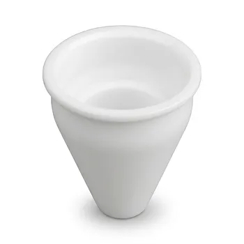
- Custom Machined PTFE Conical Sample Cell Corrosion Resistant Triangular Fluoropolymer Container for Trace Analysis
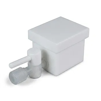
- Custom PTFE Laboratory Apparatus Corrosion Resistant Low Background Reaction Cells Precision CNC Fabrication
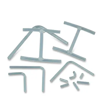
- High Performance PFA Coiled Spring Tubing and Custom PTFE Fabrication Services with Welded Fittings and Precision Bent Components
- Custom PTFE Parts Manufacturer for Teflon Containers and Components
- Customizable PTFE Rods for Advanced Industrial Applications
People Also Ask
- What customization options are available for PTFE materials? Tailor Performance for Your Application
- How do Polytetrafluoroethylene (PTFE) containers perform regarding gas permeation? Expert Insights on Solvent Absorption
- What are some common applications of machined PTFE? Leverage its Unique Properties for Demanding Applications
- How are PTFE laboratory containers and apparatus typically manufactured? Inside the Precision Machining Process
- What inherent material characteristics of non-melt-processable PTFE make it suitable for manufacturing high-purity laboratory containers and custom-machined apparatus?