ePTFE is porous PTFE; solid PTFE is dense and essentially impermeable. Solid PTFE consists of a continuous, full-density fluoropolymer matrix, while expanded PTFE contains solid polymer nodes connected by elongated fibrils, creating a three-dimensional network of microscopic pores. This structural change preserves PTFE’s chemical inertness, hydrophobicity, low friction, and broad temperature resistance while adding permeability, flexibility, lower density, and improved resistance to mechanical deformation.
The key distinction is structure: solid PTFE is best understood as a chemically resistant, low-friction solid, whereas ePTFE combines those properties with a controllable porous architecture that supports precision filtration, gas venting, conformable sealing, and flexible fluid handling.
How ePTFE and Solid PTFE Differ
Dense Matrix Versus Node-and-Fibril Network
Solid PTFE has a dense polymer structure with negligible porosity. It acts as a barrier to both gases and liquids and is commonly used where chemical containment, low friction, and dimensional stability are the primary requirements.
ePTFE is produced by controlled stretching of PTFE, which separates portions of the polymer into nodes joined by microscopic fibrils. The spacing between nodes and the geometry of the fibrils determine pore size, porosity, and permeability.
Density and Porosity
Full-density solid PTFE typically has a specific gravity near 2.1 g/cm³ and porosity below 0.1%. ePTFE can be manufactured with substantially lower density, commonly within approximately 0.1–1.0 g/cm³, and with controllable porosity ranging from roughly 25% to 96%, depending on the product and process.
This lower density reduces material mass and creates air passages through the component. The porosity can be engineered to balance flow rate, particle retention, strength, and resistance to liquid breakthrough.
Mechanical Behavior
Solid PTFE has excellent chemical and thermal resistance but is relatively susceptible to cold flow, also called creep, when subjected to sustained compressive loads. This can cause dimensional change in highly loaded seals or gaskets.
ePTFE’s fibril-reinforced structure provides high matrix tensile strength and improved resistance to deformation and flexural fatigue. Exact performance varies significantly by density and manufacturing method, but the expanded structure can support repeated flexing and conform more effectively than conventional solid PTFE.
Permeability and Electrical Properties
Solid PTFE is effectively impermeable and has the electrical behavior of a dense fluoropolymer. ePTFE contains microscopic air-filled passages, giving it air permeability and a lower effective dielectric constant and loss tangent.
The electrical difference is secondary in many filtration applications, but it can matter in components where low dielectric loading, low signal loss, or controlled venting is important.
Why the Structure Matters in Precision Filtration
Controlled Particle Retention
An ePTFE membrane can be engineered with a defined pore-size distribution. Particles larger than the effective pores are retained while gases, vapors, or compatible fluids pass through, allowing the membrane to function as a precise separation layer.
The node-and-fibril architecture provides a large filtration surface without requiring a dense bulk material. This supports efficient micro-particulate removal in laboratory sample preparation and gas or liquid filtration.
High Flow with Chemical Resistance
The interconnected pores provide pathways for air and other compatible fluids, reducing the flow restriction that would result from using solid PTFE as a barrier. At the same time, the fluoropolymer matrix resists aggressive acids, bases, organic solvents, and many other chemically challenging environments.
This combination is valuable when a filtration component must provide both controlled transport and chemical compatibility. A porous membrane can vent or filter without introducing a material that is easily attacked by the process fluid.
Selective Liquid and Gas Transport
ePTFE is hydrophobic, so it can permit gas passage while resisting penetration by water-based liquids until a sufficient pressure is applied. This behavior depends on pore size, surface condition, liquid properties, and pressure, often described using water entry pressure.
The result is useful in vent filters and protected fluid systems where gases must equilibrate or escape while liquid droplets and particulates remain contained. It should not be interpreted as universal liquid repellency: wetting liquids, surfactants, pressure, and contamination can change membrane behavior.
Reduced Contamination Risk
PTFE’s low surface energy and chemical inertness reduce adhesion and reaction with many samples. In precision laboratory systems, this can help maintain fluid purity and reduce the risk that the filtration material will contribute extractables or interact with sensitive chemicals.
The actual contamination profile still depends on the specific membrane, additives, supports, sterilization method, and operating environment.
Why ePTFE Benefits Fluid Handling Components
Flexible Sealing and Conformability
Solid PTFE is chemically robust but comparatively stiff. ePTFE’s fibrillar structure allows it to compress, flex, and conform to imperfect mating surfaces more readily.
That conformability helps ePTFE gaskets, tapes, and seal elements maintain contact across surface irregularities. It can improve leak resistance in custom apparatus exposed to corrosive chemicals or thermal cycling.
Improved Resistance to Creep
Under sustained pressure, solid PTFE can gradually deform. ePTFE is not completely immune to creep, but properly engineered grades can offer substantially better resistance to cold flow and load-related deformation.
This makes ePTFE useful where a seal must remain dimensionally stable over time. Design still needs to account for compression, temperature, pressure, flange geometry, and the material’s density.
Flexible Tubing and Dynamic Components
The high flexibility and fatigue resistance of ePTFE support applications involving repeated bending or movement, including specialized tubing and dynamic sealing components. Its low friction can also reduce sliding resistance at contact surfaces.
For peristaltic pumping or repeated flexure, the selected ePTFE construction must be matched to the required pressure, bend radius, cycle count, and chemical exposure. Porosity and wall construction can affect whether the tubing is suitable for containment or only for specialized permeable functions.
Thermal and Chemical Stability
Both materials retain PTFE’s strong resistance to aggressive chemicals, low flammability, hydrophobicity, and broad operating-temperature capability. ePTFE additionally provides lower thermal conductivity and a structure that can accommodate mechanical movement more effectively.
Published maximum service temperatures vary by grade and design. A commonly cited ePTFE limit is around 280°C, while the practical temperature limit for a finished component may be lower because of pressure, support materials, joints, and long-term mechanical loading.
Understanding the Trade-offs
Porosity Can Reduce Barrier Performance
The same pores that make ePTFE permeable also mean that it cannot replace solid PTFE when complete fluid containment is required. A membrane may allow gas transport, vapor diffusion, or selected liquid passage when a dense part is expected to block all transport.
The correct choice depends on whether the component’s primary function is separation and venting or containment and structural support.
Strength Depends on Density and Orientation
ePTFE can have high tensile strength, but its strength is not a single fixed material value. Density, fibril orientation, processing conditions, thickness, and whether the material is supported all affect performance.
A high-porosity membrane may provide excellent flow and filtration but less load-bearing capacity than a denser expanded structure. Components exposed to pressure differentials may require a backing layer, support screen, or composite construction.
Pore Fouling Can Limit Flow
Particles, precipitates, oils, and biological material can block ePTFE pores. Hydrophobic membranes may also behave differently when exposed to surfactants or low-surface-tension liquids.
Filtration design should therefore consider sample cleanliness, prefiltration, cleaning compatibility, pressure limits, and the required service life.
ePTFE Still Requires Application-Specific Design
Claims that ePTFE has no cold flow or is universally suitable for sealing are too broad. Expanded PTFE generally improves creep resistance and conformability, but sustained load, elevated temperature, pressure cycling, and flange design still determine long-term seal performance.
Likewise, chemical resistance should be verified for the actual chemical mixture, temperature, concentration, and exposure duration rather than inferred solely from the PTFE name.
Making the Right Choice for Your Goal
Select between the materials according to the function the component must perform.
- If your primary focus is precise filtration: Choose ePTFE when controlled porosity, particle retention, air permeability, and chemical resistance are required.
- If your primary focus is complete fluid containment: Choose solid PTFE when the component must remain dense and impermeable.
- If your primary focus is flexible sealing: Choose an appropriately engineered ePTFE grade when conformability, fatigue resistance, and reduced creep are more important than full density.
- If your primary focus is gas venting: Use hydrophobic ePTFE to support pressure equalization and gas flow while resisting liquid intrusion, subject to the membrane’s water-entry rating.
- If your primary focus is dynamic fluid handling: Evaluate ePTFE for flexible tubing or seals, while confirming pressure, temperature, porosity, and cycle-life requirements for the specific construction.
Understanding the node-and-fibril structure is the key to matching ePTFE’s permeability and flexibility with the containment and dimensional requirements of solid PTFE.
Summary Table:
| Property | Solid PTFE | ePTFE |
|---|---|---|
| Structure | Dense, continuous polymer matrix | Node-and-fibril network with microscopic pores |
| Density (g/cm³) | ~2.1 | 0.1–1.0 |
| Porosity | <0.1% | 25–96% |
| Permeability | Essentially impermeable | Air and compatible fluids pass through |
| Flexibility | Stiff | Flexible, conformable |
| Creep resistance | Susceptible to cold flow | Improved creep resistance |
| Typical applications | Containment, low friction, dimensional stability | Filtration, venting, sealing, dynamic components |
Optimize your filtration and fluid handling with precision PTFE components. At KINTEK, we specialize in advanced PTFE and PFA solutions, including ePTFE membranes and custom machined parts. Our expertise helps you select the right material for controlled porosity, chemical resistance, and reliable performance. Contact us today to discuss your application and discover how our high-performance fluoropolymers can enhance your processes.
Related Products
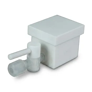
- Corrosion Resistant PTFE Evaporation Cell Electrophoresis Tank 400ml Flame Retardant Insulated Reaction Vessel Customizable
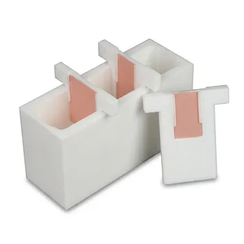
- White PTFE Electrolytic Cell with Movable Slider and Insulated Lid for Fluorine Corrosion Resistance
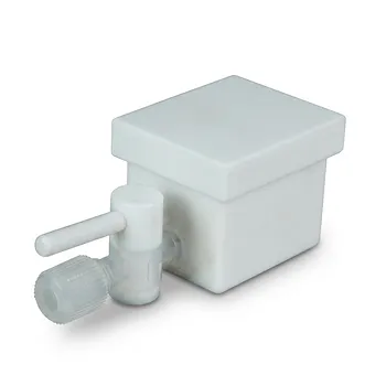
- Custom PTFE Corrosion Resistant Insulating Electrophoresis Reaction Cell with Septum and Valves for Low Background Trace Analysis
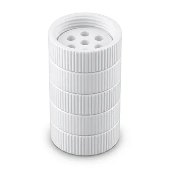
- High Temperature PTFE Reaction Sieve with Customizable Layers and Precision Pore Sizes for Threaded Sample Separation Devices
- Large Scale PTFE Beakers and Flasks for High Temperature Corrosion Resistant Laboratory Applications with Custom CNC Fabrication
People Also Ask
- Why are high-purity PTFE or PFA reaction vessels recommended for the synthesis of PANI-TiC hybrid materials? - Guide
- What reaction vessel and fluid handling considerations are necessary for living cationic polymerization of fluorinated monomers involving Lewis acid catalysts? Key design and safety tips
- How do perfluorinated solvent environments influence the selection of reaction vessels and fluid handling components in nonaqueous emulsion polymerizations? Choose fluoropolymer materials.
- Why is a high-quality PTFE reaction vessel required for the etching preparation of Ti3C2Tx MXene? Ensure Pure Synthesis.
- Why are fluoroplastic (PTFE) reaction vessels recommended for Methylene Blue (MB) adsorption kinetic experiments?