PTFE fine powder extrudates are verified by paste extrusion followed by controlled hot stretching and tensile failure testing. A resin is extruded into a uniform beading, stretched below its sintering temperature at a specified temperature and rate, and evaluated for both dimensional extensibility and load-bearing capacity. The key measurements are the Stretch Ratio (SR), Ultimate Stretch Ratio (USR), and tensile break strength.
The extrudate passes the mechanical-integrity evaluation when it can stretch to the required ratio without premature failure and still retains sufficient tensile break load—typically at least 80% of the original beading strength or at least 2.27 kgf.
How the PTFE Extrudate Is Prepared
Paste-extrude the fine powder
The PTFE fine powder is first paste-extruded through a specified orifice, such as a 0.318 cm diameter die, to produce a continuous, uniform beading.
The beading must be reasonably consistent in cross-section and free from obvious defects, because variations in mass per unit length can distort the calculated stretch ratio.
Establish the initial specimen condition
A measured length or section of the unstretched beading is weighed to determine its initial weight per unit length.
The corresponding initial tensile strength is also established by testing an unstretched specimen to failure under the specified tensile-test conditions.
How Stretch Ratio Is Tested
Stretch the beading under controlled conditions
The specimen is clamped and stretched in a circulating oven at a controlled temperature and strain rate.
A representative test condition is 300°C with a constant stretch rate of 5.33 cm/s. The test temperature must remain below the resin’s sintering or melting-related processing range so that the result reflects the resin’s stretchability rather than uncontrolled melting or sintering.
Calculate the Stretch Ratio
After stretching, the specimen is allowed to reach the defined test condition, and its weight per unit length is measured again.
Because the specimen’s mass is essentially conserved, the Stretch Ratio is calculated from the change in weight per unit length:
[ SR=\frac{\text{initial weight per unit length}} {\text{stretched weight per unit length}} ]
A lower weight per unit length after stretching indicates that the same material has been distributed over a greater length.
Under uniform deformation, this ratio corresponds approximately to the length increase ratio:
[ SR\approx\frac{L_{\text{stretched}}}{L_{\text{initial}}} ]
The weight-per-length method is useful because it evaluates the actual extrudate deformation without relying solely on manual length measurements.
How Ultimate Stretch Ratio Is Tested
Continue stretching until failure
For the Ultimate Stretch Ratio test, the beading is stretched under the same controlled temperature and rate until it breaks.
The test records the maximum extension achieved immediately before rupture.
Calculate the Ultimate Stretch Ratio
The Ultimate Stretch Ratio is calculated using the weight per unit length at the breaking condition:
[ USR=\frac{\text{initial weight per unit length}} {\text{weight per unit length immediately before break}} ]
Equivalently, when the specimen deforms uniformly:
[ USR\approx\frac{L_{\text{at break}}}{L_{\text{initial}}} ]
The USR identifies the maximum stretchability of the extrudate. It is especially useful for detecting resin or processing conditions that cause premature rupture during stretching.
How Tensile Break Strength Is Verified
Test the stretched specimen to failure
A stretched specimen is clamped in a tensile tester and pulled until it breaks.
The test records the maximum tensile load carried immediately before rupture. The result may be reported as a force, such as kilogram-force, or converted to stress if the specimen cross-sectional area is known.
Compare strength with the original beading
The stretched specimen’s break load is compared with the tensile break load of the original, unstretched beading.
A typical acceptance requirement is that the stretched specimen retain at least 80% of the original unstretched beading’s tensile break strength, with an absolute minimum of approximately 2.27 kgf, where that criterion applies.
This comparison is important because a specimen can achieve a high stretch ratio yet become mechanically weak. Stretchability alone does not demonstrate structural integrity.
What the Three Measurements Reveal
Stretch Ratio measures controlled extensibility
SR indicates how much the material can be stretched under the specified test condition.
It is primarily a measure of the extrudate’s ability to undergo the intended deformation without immediate failure.
Ultimate Stretch Ratio measures failure-limit extensibility
USR indicates the maximum stretch before rupture.
A large difference between the normal SR requirement and the USR can show that the material has useful processing tolerance, while a low USR suggests susceptibility to defects or premature breakage.
Tensile break strength measures retained integrity
Tensile break strength shows whether the stretched beading remains capable of carrying load.
This is the most direct check that stretching has not produced a mechanically inadequate structure for downstream products such as fluoropolymer tubing, custom parts, or porous media.
Understanding the Trade-offs
High stretch does not automatically mean high strength
A material may stretch extensively but have poor retained break strength if the deformation creates weak regions, discontinuities, or excessive orientation-related damage.
For that reason, SR and USR should always be interpreted together with tensile break strength.
Test conditions strongly affect the result
Temperature, stretch rate, die geometry, specimen uniformity, clamping, and measurement timing can all influence the measured ratios and break load.
Results are meaningful only when these variables are held constant and reported with the test data.
Do not confuse solid PTFE with ePTFE performance
Conventional molded, extruded, or calendared PTFE generally has very low porosity, whereas expanded PTFE can have much higher porosity and a fibril-and-node structure created by controlled high-temperature, high-rate expansion.
The tests described here verify the mechanical behavior of the fine-powder paste-extruded material under a defined stretch protocol; they do not, by themselves, fully characterize the final porosity, permeability, or strength of an ePTFE product.
How to Apply This to Your Project
The three tests should be used as a combined quality-control protocol rather than as isolated measurements.
- If your primary focus is stretch-processing capability: Measure SR under a fixed temperature and stretch rate, and confirm that the extrudate reaches the required deformation without premature failure.
- If your primary focus is maximum extensibility: Continue the test to rupture and calculate the USR from the initial and pre-break weight per unit length.
- If your primary focus is product reliability: Compare the stretched specimen’s tensile break load with the original beading and verify retention of at least 80% or the applicable minimum load of 2.27 kgf.
- If your primary focus is reproducible quality control: Standardize the die, specimen dimensions, oven temperature, stretch rate, clamping method, and calculation procedure across all batches.
Together, SR, USR, and tensile break strength show whether a PTFE fine powder extrudate is not only stretchable, but mechanically reliable after stretching.
Summary Table:
| Test | Purpose | Method | Key Metric |
|---|---|---|---|
| Stretch Ratio (SR) | Measures controlled extensibility during processing | Stretch at controlled temp/rate; weigh before/after | SR = initial weight/length / stretched weight/length |
| Ultimate Stretch Ratio (USR) | Determines maximum stretch before rupture | Stretch until break; weigh pre-break | USR = initial weight/length / weight at break |
| Tensile Break Strength | Verifies retained load-bearing capacity after stretching | Pull stretched specimen to failure; compare to original | Accept: ≥80% of original strength or ≥2.27 kgf |
Ensure your PTFE extrudates meet rigorous mechanical standards. At KINTEK, we specialize in high-performance fluoropolymers, offering precision PTFE and PFA labware, custom machining, and bespoke solutions for demanding applications. Whether you need standard components or complex custom parts, our expertise ensures reliability and consistency. Contact us today to discuss your requirements and elevate your quality control.
Related Products
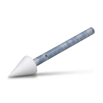
- High Temperature Resistant PTFE Solid Sampler Corrosion Resistant Non Leaching Reusable Biopharmaceutical White Powder Sampling Device
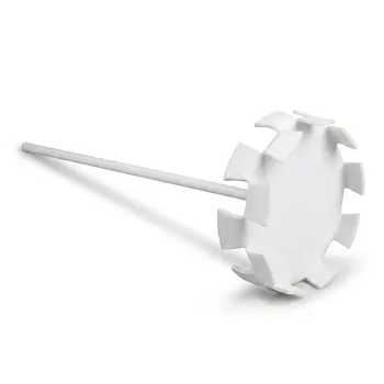
- PTFE Dispersion Disk Food Cosmetic Grade Non Stick Corrosion Resistant Large Stirring Paddle Customizable Impeller
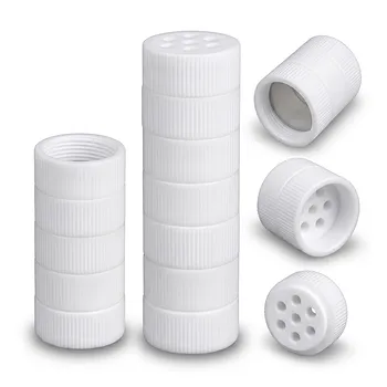
- Corrosion Resistant PTFE Multi Layer Sieve with Threaded Connections for Bio Chemical Laboratory Extraction and Customizable Mesh Size
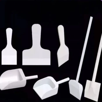
- Customizable PTFE Scrapers and Shovels for Demanding Applications
- Custom PTFE Shallow Evaporating Dishes for Diverse Applications
People Also Ask
- How does PTFE's electrical insulation property benefit electronic components? Ensure Reliability and Signal Integrity
- What process steps and conditions are critical during coagulation and drying of aqueous PTFE dispersions to ensure powder quality? Master key parameters for reliable downstream processing.
- What surface chemical species and binding energy signatures are detected on PTFE fluoropolymer sample holders during XPS analysis? Key insights for accurate calcium detection.
- What are the mechanical and safety advantages of using PTFE apparatus in a laboratory? Enhance Safety & Durability
- Why does PTFE require specialized powder processing techniques rather than standard melt-injection molding during component manufacturing? Unlock the secrets of PTFE processing.