The operating logic of a PTFE battery mold revolves around the controlled application of uniaxial pressure to transform loose powders into a structurally sound, high-density electrochemical stack. This process utilizes a hydrophobic cavity to contain battery composites while subjecting them to pressures typically ranging from 10 to 500 MPa. The cycle concludes by leveraging the material’s inherent non-stick properties to eject the finished component without compromising its geometric integrity.
The core logic of the PTFE molding cycle is to maximize material densification by confining powder laterally, ensuring that all mechanical energy is used to eliminate porosity and interlock particles before a frictionless release.
The Mechanical Foundation of the Compaction Cycle
Volumetric Powder Loading
The cycle begins by loading precise amounts of battery powders or composites into the mold's hydrophobic cavity. This environment prevents moisture interference and ensures the powder flows evenly, which is critical for achieving a uniform density across the final battery stack.
Lateral Force Containment
As the press engages, the rigid walls of the mold provide lateral confinement. By preventing the material from expanding sideways, the mold forces the applied energy downward, focusing the mechanical stress directly on the internal structure of the powder.
Uniaxial Pressure Application
A ram (or a combination of a top and bottom ram) applies uniaxial pressure to the material. In automated setups, this pressure is often higher than standard molding to compensate for shorter compression times, ensuring the powder reaches the required density quickly.
Material Transformation and Densification
Particle Deformation and Interlocking
Under extreme pressure, individual particles within the battery composite begin to deform and physically interlock. This phase is critical because it reduces internal porosity, creating the continuous pathways necessary for efficient ion and electron transport.
Maintaining Geometric Fidelity
Throughout the high-pressure phase, the mold must maintain its shape despite the immense internal forces. The structural integrity of the mold ensures that the resulting battery stack meets exact dimensional tolerances, which is vital for multi-layered cell assembly.
The Physics of Extrusion
In automated systems, the logic shifts from compression to extrusion. Once the "preform" is created, a lower ram or ejection pin pushes the dense stack out of the cavity, completing the mechanical cycle.
Understanding the Trade-offs and Limitations
The Risk of PTFE "Cold Flow"
While PTFE is prized for its non-stick properties, it is susceptible to creep or cold flow under sustained high pressure. If the mold is not properly reinforced, the cavity can subtly deform over time, leading to a loss of precision in the battery dimensions.
Thermal Sensitivity and Expansion
PTFE has a high coefficient of thermal expansion, meaning the mold's logic can be disrupted by temperature fluctuations. Changes in ambient heat can alter the clearance between the ram and the cavity, potentially leading to material leakage or "flashing."
Pressure Limits and Cycle Fatigue
Subjecting a PTFE mold to the upper limit of 500 MPa accelerates wear on the sealing surfaces. Operators must balance the need for maximum density with the reality that higher pressures shorten the operational lifespan of the mold components.
How to Apply This to Your Project
Optimizing the Compaction Strategy
- If your primary focus is maximizing energy density: Prioritize higher pressures (300-500 MPa) and longer dwell times to ensure total particle interlocking.
- If your primary focus is high-volume production: Implement an automated dual-ram system to reduce cycle times and utilize the extrusion method for faster ejection.
- If your primary focus is delicate multi-layer stacks: Utilize the non-stick hydrophobic nature of the PTFE cavity to minimize shear forces during the ejection phase.
By mastering the balance between mechanical confinement and the unique material properties of PTFE, you can produce battery components that meet the rigorous standards of modern electrochemical storage.
Summary Table:
| Stage | Operating Logic | Key Benefit |
|---|---|---|
| Powder Loading | Volumetric filling in hydrophobic cavity | Ensures uniform material flow and moisture resistance |
| Compression | Uniaxial pressure (10-500 MPa) | Eliminates porosity and drives particle interlocking |
| Containment | Rigid lateral force confinement | Focuses mechanical energy downward for max densification |
| Ejection | Frictionless release via non-stick PTFE | Maintains geometric integrity of the finished battery stack |
Elevate Your Electrochemical Research with KINTEK Precision
At KINTEK, we understand that battery performance begins with structural integrity. Whether you are navigating the complexities of uniaxial pressure or managing PTFE cold flow, our high-performance fluoropolymer solutions provide the reliability your lab demands.
From everyday basic labware like beakers, crucibles, and reagent bottles to specialized battery testing fixtures, electrochemical cells, and hydrothermal synthesis liners, we manufacture virtually all laboratory supplies crafted from premium PTFE and PFA. Backed by end-to-end custom CNC fabrication, we deliver everything from complex non-standard machined parts to high-volume orders with absolute focus on material purity and dimensional tolerance.
Ready to optimize your compaction cycles? Contact KINTEK today to discuss your custom battery mold requirements!
Related Products
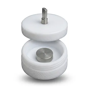
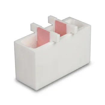
- Acid Resistant PTFE Button Cell Battery Test Fixture Customizable Machining High Purity Electrochemical Testing Clamp
- Corrosion Resistant PTFE Small Reaction Bottle One Piece Molded Teflon Sample Storage Tank
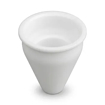
- Custom Machined PTFE Conical Sample Cell Corrosion Resistant Triangular Fluoropolymer Container for Trace Analysis
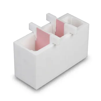
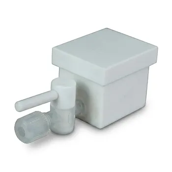
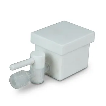
- White PTFE Electrolytic Cell with Movable Slider and Insulated Lid for Fluorine Corrosion Resistance
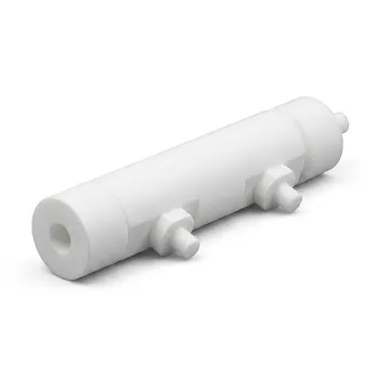
- Corrosion Resistant PTFE Electrochemical Cell for New Energy Research Inert Insulating Customizable Lab Reaction Vessel
People Also Ask
- How does the chemical inertness of PTFE benefit laboratory-scale battery testing? Ensure high-purity research results.
- What is the primary function of a PTFE battery clamp in electrochemical research? Ensure Precision & Stable Contacts
- What are the primary functions and material compositions of PTFE battery clamps? Ensure Precision & Chemical Resistance
- In what industrial manufacturing contexts are PTFE battery clamps or fixtures utilized? Optimize Battery Production.
- How do the surface properties of PTFE battery clamps improve operational efficiency? Maximize Your Lab Throughput