Sintered porous PTFE can function as both a high-temperature catalytic medium and a chemically inert structural support in CTFE dimerization. Used alone or combined with sodium fluoride or potassium fluoride, it promotes the thermal conversion of chlorotrifluoroethylene into 4,4-dichlorohexafluoro-1-butene at approximately 300 °C to 450 °C, with reported dimer yields above 90%. Its porous structure can improve contact between the reactant and catalytic components while resisting attack from aggressive fluorochemical species.
In CTFE dimerization, porous PTFE is valuable because it combines controlled porosity with exceptional fluorochemical compatibility. However, operation near or above PTFE’s melting and decomposition ranges requires careful control of temperature, residence time, pressure, and material configuration.
How Porous PTFE Supports CTFE Dimerization
Creating a High-Contact Reaction Medium
Sintered PTFE contains interconnected pores that provide pathways for gas or liquid flow through the material. This structure can increase contact between CTFE and the reactive environment compared with a solid, nonporous PTFE component.
When sodium fluoride or potassium fluoride is incorporated, the porous PTFE can act as a support matrix that distributes or retains the inorganic fluoride phase within the reaction zone.
Supporting Thermal Dimer Formation
CTFE dimerization is a high-temperature reaction in which two CTFE molecules combine to form a C4 fluorinated olefin, commonly identified as 4,4-dichlorohexafluoro-1-butene.
The porous PTFE system facilitates this reaction under thermal conditions rather than serving simply as a passive container. Depending on the formulation and operating conditions, the fluoride component may provide much of the catalytic functionality, while the PTFE contributes structure, contact area, and chemical compatibility.
Maintaining Fluid Distribution
A porous component can help distribute reactants across the active region and reduce localized flow paths. In laboratory or pilot equipment, this may make the component useful as a catalytic support, flow distributor, or packed reaction element.
The exact benefit depends on pore size, porosity, thickness, loading of sodium or potassium fluoride, and the way the component is installed in the reactor.
Why PTFE Is Attractive in Fluorochemical Processing
Resistance to Aggressive Chemistry
Fluorochemical reactions can involve reactive halogenated monomers and intermediates that attack many metals, elastomers, and conventional polymers.
PTFE is highly chemically inert toward a broad range of corrosive substances. This reduces the risk that the reaction environment will damage the support or introduce contaminants through corrosion.
Structural Use in Process Equipment
PTFE is already used in chemical-processing equipment such as linings, diaphragms, pump components, impellers, tanks, reaction vessels, autoclaves, and containers.
Sintered porous PTFE extends this materials capability into components that require controlled permeability or internal surface area, including reaction supports and fluid-distribution elements.
Minimizing Unwanted Surface Effects
Metal surfaces can participate in unwanted reactions, promote decomposition, or contaminate fluorinated products. A high-purity fluoropolymer contact surface can reduce these risks when the process and temperature remain within the material’s validated operating limits.
This does not guarantee the elimination of side reactions. Product purity also depends on reactor design, catalyst formulation, impurities, residence time, and temperature control.
Designing the Porous PTFE Reaction Component
Selecting the Pore Structure
The pore network must balance reactant access, pressure drop, mechanical strength, and catalyst retention.
Large or highly interconnected pores can improve flow but may provide less surface area or allow fluoride particles to migrate. Smaller pores can improve retention but may increase pressure drop and create diffusion limitations.
Integrating Sodium or Potassium Fluoride
Porous PTFE may be used independently or combined with sodium fluoride or potassium fluoride. In the combined configuration, the PTFE provides a stable framework for placing the inorganic fluoride within the reaction zone.
The distribution and loading of the fluoride are important. Uneven loading can create regions of excessive activity, poor conversion, or localized heat release.
Using Custom-Machined Components
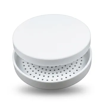
Custom-machined porous PTFE parts can be shaped to fit a specific reactor, flow path, or catalyst bed. Useful forms may include discs, sleeves, inserts, plugs, or supported porous sections.
Machining tolerances, pore damage, particle shedding, and sealing geometry should be evaluated together. A component that fits mechanically but restricts flow or sheds material can compromise the reaction.
Understanding the Trade-offs
PTFE Has Important Temperature Limits
The stated CTFE reaction range reaches temperatures at which PTFE approaches or exceeds its melting point and, at the upper end, may approach conditions where thermal degradation becomes a concern.
“Sintered” does not mean that PTFE is immune to thermal deformation or decomposition. Engineers must validate the specific porous grade, exposure duration, thermal gradients, mechanical loading, and chemical atmosphere before treating it as a long-term structural material at 300 °C to 450 °C.
Porosity Can Reduce Mechanical Strength
Compared with dense PTFE, porous PTFE generally has less material supporting mechanical loads. Pressure cycling, compression, thermal expansion, and handling can alter the pore structure or cause dimensional changes.
The component should therefore be supported by the reactor rather than relied upon as a free-standing pressure boundary unless its mechanical performance has been demonstrated.
Fluoride Addition Changes the System
Sodium fluoride and potassium fluoride can improve catalytic performance, but they also introduce a separate inorganic phase with its own particle-retention, handling, and compatibility requirements.
The fluoride should be immobilized or contained so that it does not enter downstream equipment or contaminate the product stream.
Performance Is Not Determined by Material Alone
A dimer yield above 90% reflects a complete reaction system, not merely the presence of PTFE. Conversion and selectivity depend on catalyst composition, temperature, CTFE feed conditions, residence time, mixing, pressure, and reactor geometry.
Porous PTFE should therefore be evaluated as one element of a controlled catalytic process.
How to Apply This to a Reactor
A reliable implementation begins by treating the porous PTFE part as both a materials problem and a reaction-engineering problem. The design should be tested under representative thermal and chemical exposure rather than selected solely from room-temperature compatibility data.
- If your primary focus is high CTFE conversion: Optimize the fluoride formulation, pore structure, reactant contact, and residence time together, because porous PTFE alone does not determine catalytic yield.
- If your primary focus is chemical purity: Use high-purity fluoropolymer contact components and limit metal exposure, while verifying that machining residues, fluoride particles, and degradation products are excluded.
- If your primary focus is long service life: Validate the specific PTFE grade at the actual temperature, pressure, thermal cycle, and exposure duration, with inspection for deformation, embrittlement, mass loss, and pore changes.
- If your primary focus is laboratory equipment design: Use custom porous inserts or distributors only after checking pressure drop, mechanical support, sealing, catalyst retention, and safe containment of reactive fluorochemical materials.
Sintered porous PTFE is most effective in CTFE dimerization when its porosity, chemical inertness, and structural role are engineered alongside the catalyst and reactor operating conditions.
Summary Table:
| Aspect | Role in CTFE Dimerization | Key Benefit | Considerations |
|---|---|---|---|
| Material | Sintered porous PTFE | High chemical inertness, thermal stability up to 450°C* | Validate deformation/degradation at upper limits |
| Structure | Interconnected pores | Increases contact area, improves reactant distribution | Trade-off with mechanical strength |
| Catalyst Integration | Support for NaF/KF | Enhances catalytic activity and selectivity | Ensure uniform loading and retention |
| Performance | Promotes dimer formation | Yields >90% at optimized conditions | Depends on complete reactor system |
| Application | Custom-machined inserts/discs | Fits specific reactor geometries | Check sealing, pressure drop, and shedding |
| Safety | High-purity contact surface | Minimizes contamination and side reactions | Monitor thermal and mechanical limits |
Unlock superior CTFE dimerization performance with our precision-engineered porous PTFE components. At KINTEK, we specialize in high-performance fluoropolymers, offering custom CNC machining to create porous inserts, catalyst supports, and flow distributors tailored to your reactor. Our PTFE and PFA products resist corrosion, ensure product purity, and maximize catalytic efficiency. Whether you need lab-scale prototypes or high-volume production, our team is ready to support your process. Contact us today to discuss your requirements and discover how KINTEK can enhance your catalytic reactions. Contact us now!
Related Products
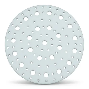
- High Temperature Resistant Insulating TFM Separator and Ultra Clean Laboratory PTFE Baffle Plate with Customizable Pore Size and Hole Configuration
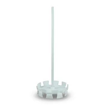
- Corrosion Resistant PTFE Dispersing Disc and High Temperature Propeller Stirring Paddle for Laboratory Chemical Mixing
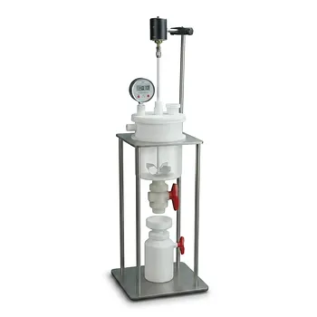
- Customizable PTFE Reaction Vessel with Electric Stirring Paddle and Buchner Funnel Vacuum Filtration System
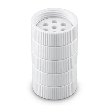
- High Temperature PTFE Reaction Sieve with Customizable Layers and Precision Pore Sizes for Threaded Sample Separation Devices
- PTFE Corrosion Resistant Filter with PFA Valve Connections and Integrated Sieve Plate
People Also Ask
- What are the limitations of pure PTFE in high temperature applications? Understanding the 200°C Ceiling
- Are Teflon parts capable of withstanding high temperatures? Understanding the 260°C Limit for Performance
- What future advancements are expected in temperature-resistant PTFE seals? Discover Smarter, Tougher Sealing Solutions
- What is porous PTFE used for? Advanced Filtration for Harsh Chemical & High-Temp Environments
- What are the benefits of porous PTFE? Unlock Superior Filtration and Chemical Resistance