Expanded PTFE (ePTFE) keeps PTFE’s chemical and thermal advantages but changes its mechanical, permeability, and electrical behavior. Solid PTFE is dense, nonporous, dimensionally stable, and electrically insulating; ePTFE contains a node-and-fibril structure with microscopic air spaces, making it lighter, more flexible, more conformable, and air-permeable. These differences generally favor ePTFE for compliant seals, venting, filtration, and low-loss high-frequency insulation, while solid PTFE remains preferable when dense barriers, predictable dimensions, and maximum impermeability are required.
The central selection issue is not whether ePTFE is “better” than solid PTFE, but whether the application benefits from controlled porosity and flexibility. Choose ePTFE when conformability, fatigue resistance, air permeability, or a lower dielectric constant matters; choose solid PTFE when density, impermeability, dimensional consistency, and simple high-temperature chemical isolation are the priorities.
What Changes When PTFE Is Expanded?
The Microstructure Creates the Difference
Solid PTFE is a continuous, full-density fluoropolymer. ePTFE is produced by stretching PTFE to form solid polymer nodes connected by elongated fibrils, leaving a network of microscopic voids.
Those voids are the source of ePTFE’s lower density, air permeability, softness, and lower effective dielectric constant. They also make its properties more dependent on density, direction of expansion, processing, and the final component design.
Physical Properties
Both materials retain PTFE’s low coefficient of friction, hydrophobicity, low flammability, broad temperature capability, and strong resistance to acids, bases, and many organic solvents.
The main physical differences are:
| Property | Solid PTFE | ePTFE |
|---|---|---|
| Structure | Dense and essentially nonporous | Microporous node-and-fibril network |
| Flexibility | Relatively stiff in bulk sections | Soft, flexible, and highly conformable |
| Density | Approximately full density | Adjustable, commonly about 0.1–1.0 g/cm³ depending on product |
| Air permeability | Essentially none | High and controllable |
| Fluid permeability | Acts as a dense barrier | Depends on pore size, pressure, surface treatment, and fluid |
| Thermal conductivity | Low | Typically even lower because of the air-filled structure |
| Chemical resistance | Excellent | Generally excellent, subject to the same application-specific limits as PTFE |
The frequently cited ePTFE porosity range of roughly 25% to 96% describes a broad class of products, not a universal value. A gasket, membrane, vent, and tubing product may have very different pore structures and performance.
Mechanical Properties
ePTFE can provide much higher matrix tensile strength than solid PTFE in the direction established by the expansion process. Reported values vary widely, with ePTFE products often cited in the range of 50–800 MPa, compared with approximately 20–30 MPa for conventional solid PTFE.
These figures should not be compared without checking the test direction, density, thickness, processing method, and test standard. ePTFE is structurally anisotropic, so tensile performance in one direction may not represent performance in another.
ePTFE also offers excellent flexural fatigue resistance and can tolerate repeated movement more effectively than many solid PTFE forms. However, component-level fatigue life still depends on bend radius, pressure, temperature, reinforcement, surface contact, and chemical exposure.
Compression, Creep, and Recovery
Unfilled solid PTFE is well known for cold flow and creep under sustained load. This can cause gasket relaxation, loss of bolt load, and dimensional change.
ePTFE’s fibrillar structure can improve resistance to deformation and provide better conformability, particularly in gasket designs. It does not eliminate creep or relaxation, however; reported gasket properties such as compressibility, recovery, and creep relaxation remain product-specific and must be evaluated under the actual load and temperature conditions.
How the Differences Affect Fluid Handling
When ePTFE Is the Better Choice
ePTFE is advantageous when a component must conform to irregular, damaged, or thermally cycling surfaces. Its flexibility allows it to fill small surface imperfections with lower sealing stress than a rigid dense material may require.
This makes ePTFE useful for gaskets, joint sealants, valve seats, pump components, flexible tubing, and filtration media exposed to aggressive chemicals. It is especially valuable where repeated flexing or installation on delicate equipment is expected.
Permeability Requires Deliberate Design
The same porosity that permits air passage can also permit liquid or gas transport under sufficient pressure. ePTFE may be air-permeable while remaining water-resistant at low pressure because surface tension and pore size restrict liquid entry.
That behavior is not equivalent to impermeability. For a pressure boundary, specify the required leak rate, pressure differential, fluid, temperature, pore structure, and any surface treatment rather than relying on the material name alone.
Filtration and Venting
ePTFE membranes can provide efficient particulate retention while allowing gas flow. This supports sterile or contamination-controlled venting, pressure equalization, and gas-liquid separation.
Solid PTFE is generally the more appropriate choice when the component must block passage entirely. ePTFE is the better choice when controlled transport is part of the function.
How the Differences Affect Sealing
Conformability Versus Dimensional Stability
ePTFE’s softness and compressibility help it seal low-pressure or irregular joints. It can accommodate surface roughness and thermal movement while maintaining contact.
Solid PTFE provides a more predictable dense barrier and can offer better dimensional stability in applications where porosity or compressibility would be undesirable. Machined solid PTFE seals may also be preferred when tight geometric tolerances are central to the design.
Load and Retention Matter
A gasket is a system involving bolt load, flange stiffness, surface finish, temperature, pressure, and chemical exposure. ePTFE can reduce sealing stress requirements, but the design still needs sufficient compression and load retention.
For high-temperature or highly pressurized service, use manufacturer compression and creep data for the specific ePTFE grade. Do not assume that high tensile strength automatically means high sealing performance.
Chemical Compatibility Is Broad, Not Unlimited
Both forms generally provide exceptional resistance to aggressive chemical environments. Nevertheless, permeation, pressure, temperature, additives, and mechanical stress can affect real-world performance.
The correct question is not only whether the polymer survives chemical contact, but whether the finished seal maintains its required leak rate and mechanical properties for the full service life.
How the Differences Affect Electrical Applications
Why ePTFE Has a Lower Dielectric Constant
Solid PTFE has a very low dielectric constant for a dense polymer, typically around 2.1 in common reference conditions. ePTFE can have a lower effective dielectric constant because part of its volume is air, whose dielectric constant is close to 1.
The exact value depends strongly on density, porosity, frequency, orientation, and measurement method. It should therefore be treated as a product specification, not as a fixed property of every ePTFE material.
Signal Integrity and High-Frequency Performance
A lower dielectric constant reduces the effective capacitance of an insulating structure and can increase electromagnetic propagation speed. A low loss tangent can also reduce dielectric loss, which is valuable in high-frequency cables, microwave structures, antennas, and interconnect systems.
These benefits can reduce signal attenuation and support controlled-impedance designs. The result depends on the complete geometry, including conductor spacing, dielectric thickness, surface roughness, manufacturing tolerances, and the surrounding materials.
Electrical Trade-offs
Porosity can make electrical performance more sensitive to compression, moisture, contamination, and manufacturing variation. Mechanical deformation can change local density and therefore alter dielectric properties or impedance.
Solid PTFE generally offers more uniform and predictable insulation properties. ePTFE is attractive when the electrical design can accommodate its lower effective dielectric constant and product-specific variability.
Understanding the Trade-offs
ePTFE Is Not a Universal Upgrade
ePTFE’s higher flexibility and porosity are benefits only when the application needs them. They can be disadvantages when the design requires a dense, impermeable, rigid, or highly dimensionally stable component.
The choice should begin with the required function: barrier, seal, vent, filter, insulator, or structural element.
Strength Data Can Be Misleading
Published ePTFE tensile strengths can be much higher than solid PTFE values, but ePTFE is direction-dependent and often has lower bulk density. A high matrix tensile value does not by itself establish resistance to burst, extrusion, compression, or wear.
Compare component-level test data using the same geometry, direction, temperature, pressure, and test method.
Temperature Ratings Need Context
Reference data often place maximum service temperatures near 260°C for solid PTFE and up to approximately 280°C for some ePTFE products. These values are not universal ratings for every grade or component.
Continuous exposure, pressure, mechanical load, thermal cycling, and chemical environment can reduce the practical operating limit. The finished component’s rating should control procurement and design decisions.
Porosity Can Increase Permeation
ePTFE’s pores may enable gas flow or fluid permeation that would be negligible through solid PTFE. This matters for volatile chemicals, pressurized gases, vacuum systems, and applications where contamination or product loss is unacceptable.
A material can be chemically compatible yet functionally unsuitable because it leaks or allows unacceptable permeation.
Making the Right Choice for Your Goal
Start with the required barrier behavior, load conditions, temperature, pressure, chemical exposure, and electrical frequency range.
- If your primary focus is chemical fluid handling: Choose ePTFE when flexibility, conformability, fatigue resistance, or controlled venting improves the component; choose dense solid PTFE when complete impermeability and predictable dimensions are more important.
- If your primary focus is sealing: Choose ePTFE for irregular surfaces, low sealing stress, thermal cycling, or repeated movement, using product-specific compression and creep data to size the joint.
- If your primary focus is filtration or pressure equalization: Choose ePTFE when controlled air or gas permeability and particulate retention are required, and verify pore size, liquid breakthrough pressure, and leak rate.
- If your primary focus is high-frequency electrical performance: Choose ePTFE when its lower effective dielectric constant and low loss support the impedance and attenuation targets, while controlling density, moisture, compression, and process variation.
- If your primary focus is rigid electrical insulation or a dense chemical barrier: Choose solid PTFE when uniform dielectric behavior, low permeability, and dimensional stability outweigh ePTFE’s flexibility and lower dielectric constant.
The most reliable selection is the one that matches the material’s structure to the component’s required function, rather than choosing between ePTFE and solid PTFE by general material reputation alone.
Summary Table:
| Property | Solid PTFE | ePTFE |
|---|---|---|
| Structure | Dense, nonporous | Microporous, node-and-fibril |
| Density | ~2.2 g/cm³ | 0.1–1.0 g/cm³ (adjustable) |
| Flexibility | Relatively stiff | Soft, flexible, conformable |
| Air permeability | None | High, controllable |
| Dielectric constant | ~2.1 | Lower (air-filled) |
| Tensile strength | 20–30 MPa | 50–800 MPa (directional) |
| Applications | Dense barriers, rigid insulators | Gaskets, seals, vents, filters, high-frequency insulators |
Need help selecting between ePTFE and solid PTFE for your specific application? Our experts at KINTEK can guide you through material selection and custom manufacturing. With our comprehensive range of PTFE and PFA lab supplies, from basic labware to advanced electrochemical cells, we offer tailored solutions for your fluid handling, sealing, and electrical needs. Contact us today for a consultation and discover how our high-performance fluoropolymers can optimize your processes. Get in touch with our team.
Related Products
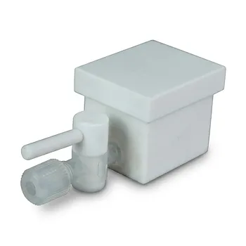
- Corrosion Resistant PTFE Evaporation Cell Electrophoresis Tank 400ml Flame Retardant Insulated Reaction Vessel Customizable
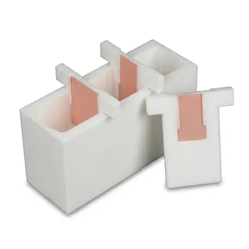
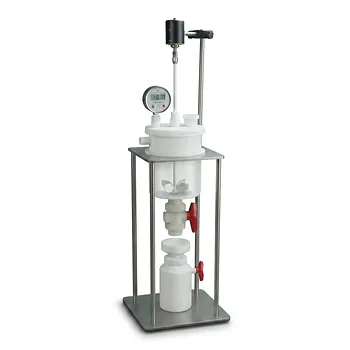
- White PTFE Electrolytic Cell with Movable Slider and Insulated Lid for Fluorine Corrosion Resistance
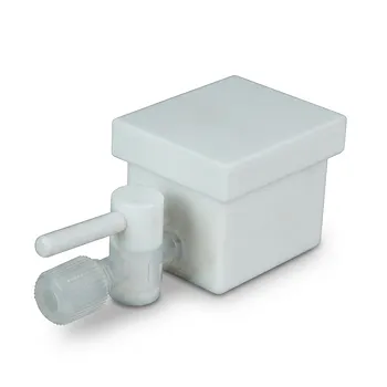
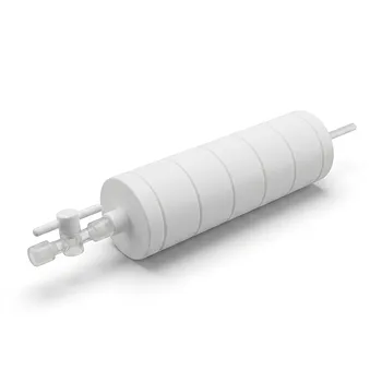
- Custom PTFE Corrosion Resistant Insulating Electrophoresis Reaction Cell with Septum and Valves for Low Background Trace Analysis
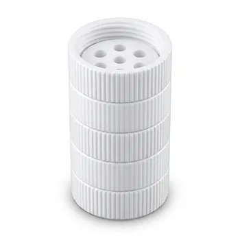
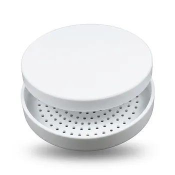
- High Temperature PTFE Reaction Sieve with Customizable Layers and Precision Pore Sizes for Threaded Sample Separation Devices
- Large Scale PTFE Beakers and Flasks for High Temperature Corrosion Resistant Laboratory Applications with Custom CNC Fabrication
People Also Ask
- What reaction vessel and fluid handling considerations are necessary for living cationic polymerization of fluorinated monomers involving Lewis acid catalysts? Key design and safety tips
- Why are high-purity PTFE or PFA reaction vessels recommended for the synthesis of PANI-TiC hybrid materials? - Guide
- Why is a high-quality PTFE reaction vessel required for the etching preparation of Ti3C2Tx MXene? Ensure Pure Synthesis.
- How do perfluorinated solvent environments influence the selection of reaction vessels and fluid handling components in nonaqueous emulsion polymerizations? Choose fluoropolymer materials.
- Why are fluoroplastic (PTFE) reaction vessels recommended for Methylene Blue (MB) adsorption kinetic experiments?