The most direct way to suppress C₄F₈ formation is to co-feed a controlled amount of perfluorocyclobutane with chlorodifluoromethane. During CF₂HCl pyrolysis, adjust the C₄F₈ concentration in the reactor feed to approximately 9.0–9.9% on the validated process basis. At this range, additional C₄F₈ formation can approach zero, improving recovery of TFE and HFP.
Core takeaway: C₄F₈ co-feed shifts the pyrolysis equilibrium so that the reactor produces little or no net additional dimer. The co-fed C₄F₈ remains largely unconsumed, so the objective is to minimize fresh dimer generation—not necessarily to eliminate C₄F₈ from the overall material balance.
Why C₄F₈ Co-Feed Works
It changes the reaction equilibrium
Perfluorocyclobutane is a dimeric byproduct formed during chlorodifluoromethane pyrolysis. Introducing C₄F₈ into the feed changes the reactor’s fluorocarbon composition and shifts the equilibrium against further net dimer formation.
The practical result is a reduction in the amount of newly generated C₄F₈ while the desired monomer products remain recoverable.
It protects valuable fluorocarbon feedstock
Without suppression, part of the CF₂HCl-derived fluorocarbon material is diverted into C₄F₈ rather than TFE. Co-feeding C₄F₈ reduces this incremental loss and can therefore improve the effective yield of TFE and HFP.
The target is a narrow operating window
The referenced optimum is approximately 9.0–9.9% C₄F₈ in the feed, where net dimer production can fall to zero.
The concentration basis must be defined carefully. Weight percent and mole percent are not interchangeable, so the process should select one basis, convert all feed-control calculations consistently, and confirm the optimum experimentally through reactor outlet analysis.
How to Implement the Suppression Strategy
Meter C₄F₈ into the CF₂HCl feed
Use a controlled C₄F₈ stream blended with the chlorodifluoromethane before the pyrolysis reactor. The blend should be stable and sufficiently mixed to prevent local composition fluctuations.
A precise gas metering system is essential because the effective operating window is relatively narrow.
Control the feed ratio, not merely the absolute flow
The relevant variable is the C₄F₈ concentration relative to the total reactor feed. Changes in CF₂HCl throughput, dilution, recycle, or pressure can alter the actual composition even if the C₄F₈ flow remains constant.
Feed-control logic should therefore calculate composition continuously from calibrated flow measurements.
Verify performance at the reactor outlet
Gas chromatography should be used to measure C₄F₈, TFE, HFP, and relevant feed components. The key performance indicator is net C₄F₈ production, determined by comparing outlet C₄F₈ with the amount introduced in the feed.
The target condition is not simply a high outlet C₄F₈ concentration. It is an outlet amount consistent with the co-fed quantity and little or no additional dimer generation.
Use compatible transfer equipment
Fluorocarbon service and high-temperature pyrolysis systems require equipment selected for chemical compatibility, temperature, and pressure conditions. PTFE or PFA transfer lines are identified in the references as suitable corrosion-resistant choices for gas delivery and sampling arrangements.
High-purity vessels and clean sample paths also help prevent contamination that could distort gas-chromatographic measurements.
How to Confirm Maximum TFE Recovery
Establish a controlled concentration sweep
Rather than assuming the target applies identically to every reactor, test a controlled series of C₄F₈ feed concentrations around the reported 9.0–9.9% range.
For each condition, measure:
- TFE production and recovery
- HFP production and recovery
- Net C₄F₈ generation
- Unconverted CF₂HCl
- Overall fluorocarbon material balance
The best operating point is the condition that minimizes net C₄F₈ formation while maintaining the desired TFE and HFP output.
Track net rather than gross dimer
Because C₄F₈ is deliberately added to the feed, a high outlet C₄F₈ concentration does not by itself indicate poor suppression. The correct calculation is:
Net C₄F₈ formation = C₄F₈ leaving the reactor − C₄F₈ introduced in the feed
This distinction prevents operators from incorrectly rejecting the co-feed strategy based only on outlet concentration.
Recheck the optimum after process changes
The effective optimum can depend on reactor configuration, residence time, temperature profile, feed composition, and analytical calibration. Any significant process change should trigger a renewed concentration check rather than relying on the original set point.
Understanding the Trade-offs
Co-feeding reduces net formation but does not remove C₄F₈
The co-fed dimer is expected to remain unconsumed according to the reference. Consequently, the process may still circulate or handle a substantial C₄F₈ inventory.
The improvement is in net production and feedstock utilization, not necessarily in total C₄F₈ flow through the plant.
Excessive co-feed can reduce process efficiency
Operating above the validated range may increase inert or nonproductive fluorocarbon loading, affect throughput, and complicate downstream separation. The 9.0–9.9% range should therefore be treated as a process-development target, not an unconditional universal set point.
Analytical error can obscure the result
Small errors in gas dosing, sampling, calibration, or composition-basis conversion can make net dimer formation appear higher or lower than it actually is.
Use calibrated flow devices, consistent composition units, corrosion-resistant sample lines, and regular gas-chromatographic verification.
Safety and materials compatibility remain fundamental
CF₂HCl, fluorocarbon products, and pyrolysis effluent require engineered containment, ventilation, pressure relief, and procedures appropriate to the specific process. High-temperature fluorochemical service also demands careful materials selection and inspection for corrosion or permeation.
Applying the Strategy to Your Process
Begin with a defined feed-composition basis, then validate the co-feed target using reactor-outlet gas chromatography and a complete material balance.
- If your primary focus is maximum TFE recovery: Set up controlled C₄F₈ co-feeding near the validated 9.0–9.9% range and optimize for minimum net dimer formation rather than minimum outlet C₄F₈ concentration.
- If your primary focus is HFP production: Evaluate TFE and HFP together because the co-feed strategy is intended to improve recovery of both desired products.
- If your primary focus is stable plant operation: Use ratio-based flow control, corrosion-resistant PTFE/PFA transfer hardware, and continuous or frequent gas-chromographic verification.
- If your primary focus is accurate scale-up: Treat the reported concentration as an operating target to be confirmed for your reactor, and do not interchange wt% and mol% without an explicit conversion.
By controlling C₄F₈ co-feed precisely and measuring net rather than gross dimer production, engineers can improve TFE recovery while maintaining a defensible fluorocarbon material balance.
Summary Table:
| Strategy | Key Action | Target/Basis |
|---|---|---|
| C₄F₈ Co-feed | Introduce controlled C₄F₈ stream into CF₂HCl feed | 9.0–9.9% (consistent basis: wt% or mol%) |
| Feed Ratio Control | Continuously calculate composition from calibrated flow measurements | Adjust to maintain target concentration |
| Performance Verification | Use gas chromatography at reactor outlet | Monitor net C₄F₈ formation (outlet minus feed) |
| Material Compatibility | Use PTFE/PFA transfer lines and high-purity vessels | Prevent contamination and corrosion |
| Process Validation | Conduct concentration sweep around target range | Optimize for minimal net dimer and desired product yields |
Optimize your CF₂HCl pyrolysis process with precision-engineered PTFE/PFA solutions from KINTEK. Our high-purity fluoropolymer components ensure accurate feed control and reliable gas sampling, helping you maximize TFE recovery. Backed by our custom CNC machining capabilities, we deliver tailored labware, transfer lines, and reaction vessels to meet your exact specifications. Contact us today to enhance your process efficiency and product yield — get in touch!
Related Products
- Custom PTFE Wide Mouth Reagent Reaction Bottle Corrosion Resistant High Temperature Large Capacity Straight Body Laboratory Vessel
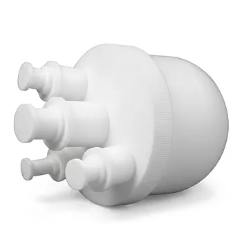
- High Purity PTFE Single Neck Reaction Flask Acid Resistant Customizable Fluoropolymer Laboratory Reactor
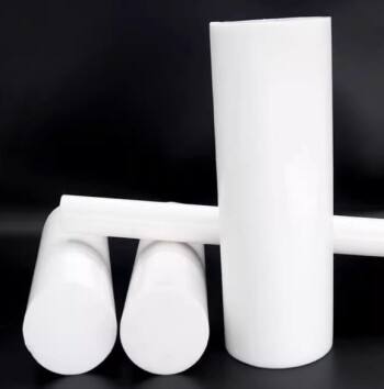
- Customizable PTFE Rods for Advanced Industrial Applications
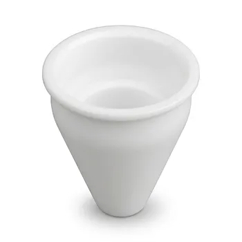
- Custom Machined PTFE Conical Sample Cell Corrosion Resistant Triangular Fluoropolymer Container for Trace Analysis
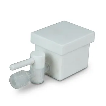
- Custom PTFE Corrosion Resistant Insulating Electrophoresis Reaction Cell with Septum and Valves for Low Background Trace Analysis
People Also Ask
- What are the key features of PTFE reagent bottles? Superior Chemical Resistance and Durability
- What are the features of PTFE laboratory bottles? Unmatched Chemical Resistance & Extreme Temperature Tolerance
- What are the advantages of using PTFE laboratory bottles? Unmatched Chemical Resistance for Critical Samples
- What are the main advantages of PTFE as a material for laboratory bottles? Superior Chemical & Thermal Resistance
- What are the advantages of the PTFE bottle's non-stick surface? Ensure Purity and Efficiency in Your Lab