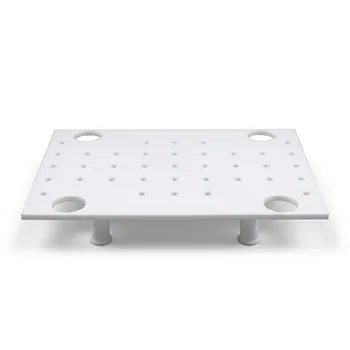
Polytetrafluoroethylene (PTFE) molds are essential for battery prototyping because they provide a chemically inert and electrically insulating environment. By using PTFE, researchers can handle highly reactive sodium and lithium compounds without risk of degradation or contamination. This material ensures repeatable pellet geometry and preserves the purity of the active materials, which is critical for accurate electrochemical performance testing.
The use of PTFE molds in battery prototyping ensures the chemical and structural integrity of reactive components by combining extreme inertness with superior electrical insulation. This prevents contamination and mechanical damage, allowing for the precise measurement of interfacial quality in next-generation energy storage.
Maintaining Chemical and Material Purity
Resistance to Reactive Sodium and Lithium
PTFE features strong carbon-fluorine bonds, making it exceptionally stable when in contact with moisture-sensitive sodium or lithium compounds. Unlike many materials that might react or degrade in inert atmospheres, PTFE remains chemically indifferent to these highly reactive metals and salts.
Prevention of Ion Leaching and Swelling
Because the material does not swell or leach ions, it prevents the electrode contamination that often plagues metal or lower-grade plastic tooling. This stability ensures that the measurements taken during testing reflect the true properties of the battery materials rather than impurities introduced by the mold.
Compatibility with Aggressive Electrolytes
PTFE molds can withstand exposure to aggressive electrolytes, including organic carbonate solvents, ionic liquids, and strong acids. This versatility allows researchers to test a wide variety of chemistries, from standard lithium-ion to advanced solid-state designs, without changing their tooling.
Optimizing Mechanical and Interfacial Integrity
Low Surface Energy and Non-Stick Properties
The intrinsic non-stick characteristics and low surface energy of PTFE prevent powder adhesion during the compaction process. This is vital for preserving fragile solid-solid interfaces, which are the primary pathways for ion transport in solid-state batteries.
Reproducible Densification and Demolding
PTFE allows for consistent material densification under high pressure without causing mechanical damage to the components during demolding. Its low coefficient of friction (0.05–0.10) ensures that precision specimens can be removed without the formation of micro-cracks or surface defects.
Support for Solvent-Free Manufacturing
These molds are highly compatible with dry-electrode processing, providing a contamination-free interface for fibrillating binders. This capability supports the development of high energy-density cells that aim to exceed 300 Wh/kg in prototype stages.
Electrical and Thermal Considerations
Prevention of Internal Short Circuits
PTFE provides a significant dielectric barrier with a strength of approximately 60 MV/m. When used as a liner within conductive metal molds, it acts as an electrical insulator that prevents internal short circuits between current collectors during high-pressure assembly.
Stability Across Wide Temperature Ranges
The material maintains its integrity and performance across a broad temperature spectrum, from –200 °C to +260 °C. This thermal stability allows for battery testing and assembly under various environmental conditions without the risk of the mold warping or losing its non-stick properties.
Understanding the Trade-offs
Mechanical Deformation (Cold Flow)
One primary limitation of PTFE is its tendency to undergo "cold flow" or creep under sustained high pressure. While it is excellent for shaping, it may deform over time if used as a structural load-bearing component without a metal sleeve or support.
Thermal Expansion Limits
Although PTFE is thermally stable, it has a high coefficient of thermal expansion compared to metals or ceramics. Rapid temperature changes can lead to dimensional shifts, which may affect the precision of the pellet geometry if not carefully managed.
Surface Hardness
PTFE is a relatively soft material, meaning it can be easily scratched or indented by hard ceramic particles or metal tools. Once the surface is compromised, the non-stick benefits may decrease, and the risk of material entrapment increases.
Making the Right Choice for Your Goal
Whether you are developing solid-state electrolytes or high-nickel cathodes, selecting the right mold configuration is essential for data integrity.
- If your primary focus is solid-state battery interfaces: Use PTFE molds to ensure a non-stick release that preserves the delicate contact between the electrolyte and the electrode.
- If your primary focus is high-pressure cell assembly: Utilize PTFE as a liner within a stainless steel mold to provide necessary electrical insulation while maintaining structural rigidity.
- If your primary focus is testing aggressive liquid electrolytes: Leverage the extreme chemical inertness of PTFE to prevent ion leaching and ensure long-term measurement stability.
By integrating PTFE molds into your prototyping workflow, you eliminate variables that compromise the purity and performance of your energy storage research.
Summary Table:
| Key Benefit | Technical Advantage | Impact on Battery Prototyping |
|---|---|---|
| Chemical Inertness | Resistant to reactive Na, Li, and aggressive electrolytes | Prevents contamination and ensures material purity. |
| Non-Stick Surface | Low surface energy (friction coeff. 0.05–0.10) | Preserves fragile solid-state interfaces; prevents micro-cracks. |
| Electrical Insulation | High dielectric strength (~60 MV/m) | Prevents internal short circuits during high-pressure assembly. |
| Thermal Stability | Operates from -200°C to +260°C | Maintains integrity during environmental testing and cycling. |
| Material Purity | Zero ion leaching or swelling | Ensures electrochemical data reflects true material properties. |
Elevate Your Battery Research with KINTEK’s Precision Fluoropolymer Solutions
Achieving breakthrough results in next-generation energy storage requires materials that never compromise your data. KINTEK specializes in high-performance PTFE and PFA laboratory supplies designed for the most demanding electrochemical environments.
Whether you need everyday essentials like beakers, crucibles, and reagent bottles, or advanced battery testing fixtures, hydrothermal synthesis liners, and custom electrochemical cells, we deliver the chemical inertness and precision your prototyping demands. Our capabilities extend from high-purity trace analysis tools and fluid transfer components to end-to-end custom CNC fabrication for complex, non-standard machined parts.
Don’t let material contamination or mechanical defects stall your innovation. Trust the experts in high-performance fluoropolymers to provide the bespoke laboratory setups and high-volume orders you need.
Contact KINTEK Today to Request a Quote for Your Custom PTFE Battery Molds!
Related Products
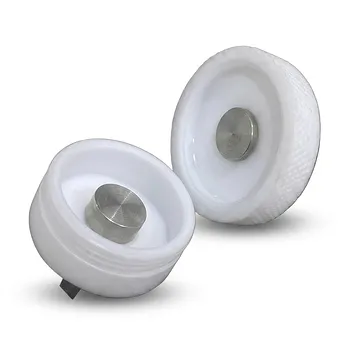
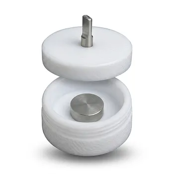
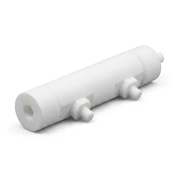
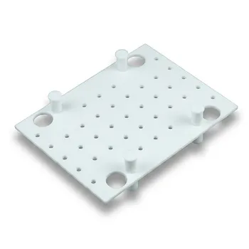
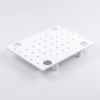
- Corrosion Resistant PTFE Coin Cell Battery Testing Clamps and Acid Proof Custom Fluoropolymer Battery Fixtures
- Acid Resistant PTFE Button Cell Battery Test Fixture Customizable Machining High Purity Electrochemical Testing Clamp
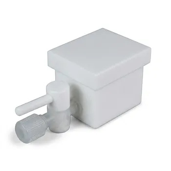
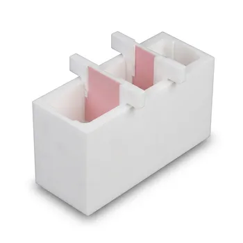
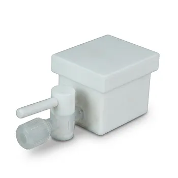
- Custom PTFE Laboratory Apparatus Corrosion Resistant Low Background Reaction Cells Precision CNC Fabrication
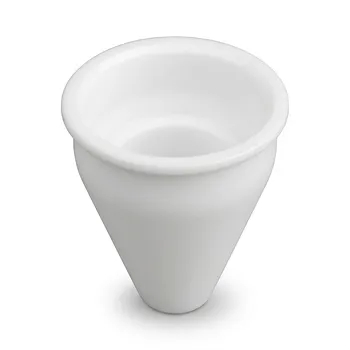
- Custom Machined PTFE Conical Sample Cell Corrosion Resistant Triangular Fluoropolymer Container for Trace Analysis
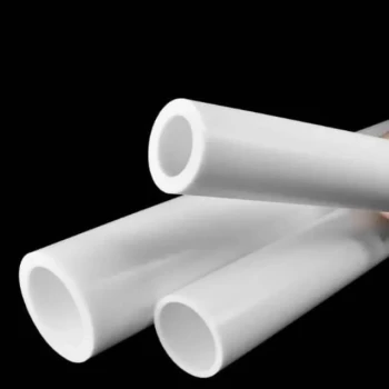
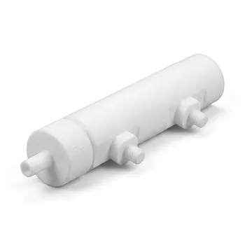
- Custom PTFE Sleeves and Hollow Rods for Advanced Applications
People Also Ask
- What are the primary functions and material compositions of PTFE battery clamps? Ensure Precision & Chemical Resistance
- How do the different electrode gripping mechanisms in PTFE battery clamps function? Optimize Your Battery Research
- What are the electrical insulation and signal integrity advantages of using PTFE battery clamps? Ensure Data Accuracy
- How does the structural design of a PTFE battery clamp minimize electrical noise? Precision Engineering for Clean Data
- In what ways do PTFE battery testing fixtures enhance laboratory throughput and reliability? Maximize Research Efficiency