ePTFE membrane crushability is evaluated by measuring how much its thickness decreases under a controlled compressive load. A specimen is secured under a mild baseline tensile load, such as 2.2 N, and its original thickness, t, is recorded. A static weight, such as 680 g applied over a 7.5 mm² area for 0.5 minutes, is then used to produce the loaded thickness, C. Crushability is calculated as ((t - C) / t) * 100%; a lower percentage indicates greater resistance to compression.
The key principle is simple: the less an ePTFE membrane compresses under a defined load, the better it can preserve its porous structure, permeability, and sealing performance during service.
How Crushability Is Evaluated
Establishing the Baseline Thickness
The membrane specimen is first secured under a controlled, mild tensile load. This helps hold the material in a consistent condition while its original, unloaded thickness is measured as t.
The baseline load matters because membrane thickness can vary with handling, tension, and positioning. Consistent specimen preparation improves the comparability of test results.
Applying a Controlled Compressive Load
A static weight is applied to a defined area of the membrane for a specified period. One example uses a 680 g load over 7.5 mm² for 0.5 minutes, producing the compressed thickness C.
These conditions define the severity of the test. In formal product qualification, the load, contact area, dwell time, temperature, and specimen geometry should be controlled and documented.
Calculating the Crushability Percentage
The thickness reduction is calculated using:
Crushability (%) = ((t - C) / t) * 100%
For example, if the membrane begins at 1.00 mm and measures 0.85 mm under load, its crushability is 15%.
The result represents the proportion of the original thickness lost during the test. It is a comparative material property under the selected test conditions, rather than a universal value independent of test method.
Interpreting the Result
A lower crushability percentage means the membrane retains more of its original thickness under compression. This indicates higher crush resistance.
A higher percentage means greater thickness loss and a greater possibility that the membrane's internal structure will be altered during assembly or operation.
Why Crush Resistance Matters in Sealing Products
Preserving the Porous Micro-Structure
ePTFE derives important performance characteristics from its porous micro-structure. Excessive compression can reduce or collapse portions of that structure.
When the structure remains stable, the material is more likely to retain its intended combination of flexibility, compressibility, and resistance to unwanted fluid passage.
Maintaining Sealing Efficacy
Fluoropolymer gaskets may experience compressive forces from bolted joints, clamps, thermal cycling, or pressure changes. If the gasket crushes excessively, its thickness and contact geometry can change.
Those changes can reduce the ability of the gasket to maintain uniform contact with mating surfaces. Higher crush resistance helps preserve sealing performance over the operating life of the component.
Supporting Consistent Custom Gasket Design
Custom gaskets often depend on predictable thickness and controlled deformation. Crushability data helps engineers determine whether a membrane can tolerate the intended assembly load without excessive permanent or temporary compression.
This is particularly important where dimensional stability, low leakage, and repeatable installation are required.
Why Crush Resistance Matters in Filtration Products
Retaining Fluid Permeability
Filtration membranes must allow the intended fluid flow through their pore structure. Compression that closes or distorts pores can reduce permeability.
A membrane with higher crush resistance is better positioned to preserve its flow characteristics when exposed to mechanical pressure or a pressure differential.
Maintaining Filtration Behavior
Changes to pore geometry can affect more than flow rate. They may also change how the membrane interacts with particles, gases, or liquids passing through it.
Maintaining the original porous structure supports more consistent filtration performance throughout the operating range.
Withstanding Support and Assembly Forces
Filtration media may be laminated to support layers, compressed into housings, or held between other components. These conditions can impose localized or distributed loads on the membrane.
Crush resistance provides an indication of how well the material can tolerate those forces without losing the functional structure needed for filtration.
Understanding the Trade-Offs
Crush Resistance Is Not the Only Design Criterion
A low crushability result is valuable, but it does not by itself establish that a membrane is suitable for every gasket or filtration application. Engineers must also consider chemical compatibility, temperature, permeability, tensile strength, leakage requirements, and long-term durability.
The correct material is the one that satisfies the complete application profile.
Test Conditions Affect the Result
Crushability depends on how the test is performed. Load magnitude, loaded area, dwell time, temperature, specimen handling, and initial tension can all influence the measured thickness reduction.
Results should therefore be compared only when the test conditions are equivalent or when the differences are understood.
Short-Term Compression Does Not Predict Every Failure Mode
A static thickness test measures response to a defined compressive event. It may not fully represent repeated loading, vibration, thermal cycling, creep, relaxation, or long-term pressure exposure.
For critical products, crushability testing should be combined with application-specific sealing or filtration validation.
Excessive Compression Can Have System-Level Effects
A crushed gasket may no longer provide the intended seal, while a crushed filter may develop excessive flow resistance. In either case, the issue is not merely a change in thickness; it is a change in system behavior.
Testing should connect the material result to measurable product requirements such as leakage rate, pressure drop, or flow stability.
Making the Right Choice for Your Goal
Use crushability as a screening and quality-control metric, then confirm the selected material under realistic service conditions.
- If your primary focus is sealing reliability: Choose an ePTFE membrane with a low crushability percentage and verify that it maintains contact pressure and leakage performance under the actual assembly load.
- If your primary focus is filtration performance: Choose a membrane with sufficient crush resistance to preserve permeability and pore structure under the expected pressure differential and support conditions.
- If your primary focus is material comparison: Test all candidates using the same specimen preparation, load, contact area, dwell time, and measurement procedure.
- If your primary focus is product qualification: Combine crushability results with application-specific tests for leakage, pressure drop, flow, temperature exposure, and long-term compression behavior.
A well-controlled crushability measurement helps predict whether an ePTFE product will retain the structure and performance required by its sealing or filtration application.
Summary Table:
| Aspect | Evaluation Method | Why It Matters |
|---|---|---|
| Test Setup | Specimen secured under baseline tensile load (e.g., 2.2 N) | Ensures consistent starting thickness |
| Compression | Static weight (e.g., 680 g) applied to defined area (e.g., 7.5 mm²) for set time | Simulates real-world compressive forces |
| Calculation | Crushability (%) = ((t - C) / t) × 100% | Quantifies thickness loss under load |
| Performance | Lower crushability % = higher resistance | Preserves porous structure, permeability, and sealing integrity |
Optimize your sealing and filtration solutions with high-performance ePTFE membranes. At KINTEK, we specialize in precision-engineered PTFE and PFA products, including custom membranes that resist crushing while maintaining permeability. Contact us today to discuss your specific requirements and benefit from our expert support, OEM/ODM capabilities, and reliable supply.
Related Products
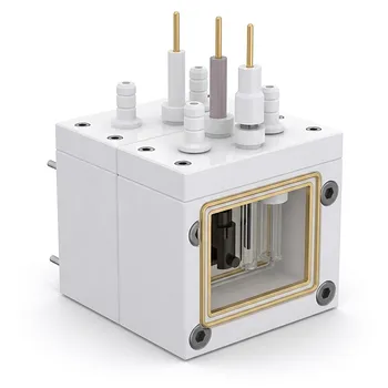
- All PTFE Exchangeable Membrane Electrochemical Cell Dual Chamber Three Electrode Photoelectrochemical Cell for Laboratory Trace Analysis
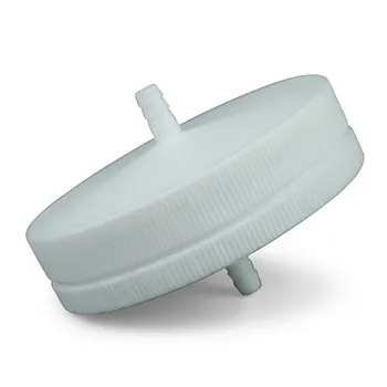
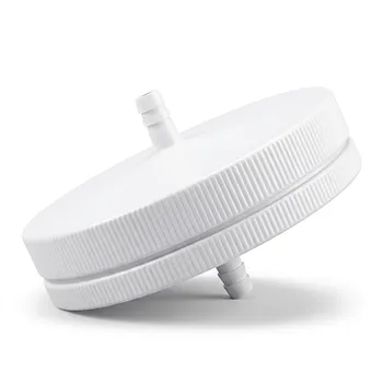
- PTFE Membrane Filter Holder for Aerosol Environmental Monitoring and Low Concentration Particulate Matter Sampling Chemical Resistant Air Quality Analysis Component
- PTFE Filter Membrane Holder for Hydrogen Chloride and Water Filtration 90mm Environmental Sampling Clamp Customizable
- High Purity PTFE Square Membrane Cutter Equipartition Device for Trace Analysis and Disease Control Centers Clean Non Stick No Leaching
- PTFE Filter Membrane Holder 47mm Leak Proof Corrosion Resistant Environmental Sampling Unit Customizable
People Also Ask
- What makes PTFE an ideal construction material for custom electrochemical cells and electronic analytical instrumentation housings? Discover superior chemical resistance and electrical insulation
- Why are high-performance fluoropolymers like PTFE and PFA preferred for electrochemical cells and sensitive analytical instrumentation? Achieve Reliable, Contamination-Free Measurements
- What material properties allow fluoropolymers to withstand extreme heat and corrosion? Discover how PTFE and PFA ensure inertness, stability, and purity for demanding lab applications.
- What structural features enable ePTFE membranes to deliver effective filtration and chemical resistance?
- How does the electroactive β-phase in fluoropolymer battery separators enhance lithium-ion transport, and why are custom electrochemical cells necessary for evaluating these membrane performance characteristics?