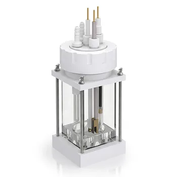
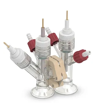
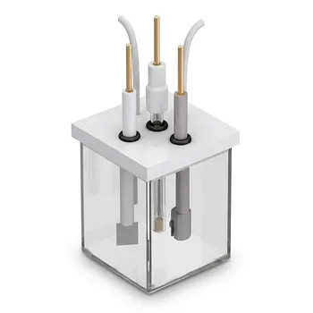
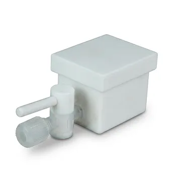
The decomposition of PFOA is governed primarily by the anode material, applied current density, supporting electrolyte, reaction time, and cell geometry. Effective systems commonly use Ti/SnO₂-Sb or Ti/SnO₂-Sb/PbO₂ anodes, a constant current density around 10 mA/cm², and a supporting electrolyte such as NaClO₄. Under suitable conditions, PFOA degradation can follow pseudo-first-order kinetics, with reported degradation above 90% and defluorination up to 77% within 90 minutes.
PFOA removal and actual mineralization are separate outcomes: degradation measures disappearance of the parent molecule, while defluorination measures release of fluoride from its carbon-fluorine bonds. Custom PTFE cells improve the reliability of both measurements by providing an inert, sealed, electrically insulating environment that does not introduce competing reactions or contamination.
Which Parameters Control PFOA Decomposition?
Anode Composition Determines Oxidation Performance
The anode is the principal reaction surface for PFOA decomposition. Materials such as Ti/SnO₂-Sb and Ti/SnO₂-Sb/PbO₂ are used because their surface chemistry supports the oxidative processes required to attack the highly stable perfluorinated structure.
The electrode composition affects degradation rate, defluorination efficiency, current utilization, and the formation or persistence of reaction intermediates. Therefore, a high PFOA disappearance rate does not automatically indicate complete destruction of fluorinated carbon.
Current Density Controls the Electrochemical Driving Force
Applied current density determines how much electrochemical charge is delivered per unit electrode area. A constant value such as 10 mA/cm² provides a controlled basis for comparing electrode materials and operating conditions.
Increasing current density can change the rate of PFOA conversion and the relative importance of direct electrode reactions versus oxidizing species generated in the solution. The useful operating range must therefore be established experimentally rather than inferred from current alone.
Supporting Electrolyte Controls Conductivity
A supporting electrolyte such as NaClO₄ improves solution conductivity and helps maintain a stable current distribution. This allows the applied electrical conditions to be transferred more consistently to the electrode surfaces.
The electrolyte must also be chemically compatible with the electrode and cell. It should not introduce unwanted redox reactions, interfere with fluoride analysis, or produce reaction products that obscure the mechanism being studied.
Reaction Time Determines the Extent of Conversion
PFOA decomposition is time-dependent. Experiments conducted for approximately 90 minutes under optimized conditions have produced degradation ratios exceeding 90%, with defluorination rates reaching approximately 77%.
The difference between these values is important. It indicates that some PFOA-derived compounds may disappear from analytical measurements before all organically bound fluorine has been converted to fluoride.
Electrode Arrangement Affects Mass Transfer
Electrode spacing and configuration influence the electrical field, current distribution, and transport of PFOA and intermediates through the solution. These factors affect how efficiently compounds reach reactive electrode regions.
A cell that fixes electrode positions and spacing makes results more reproducible. It also allows researchers to compare experiments without introducing uncontrolled changes in the reaction geometry.
Reaction Kinetics Provide a Comparison Framework
PFOA decomposition under suitable conditions can be described using pseudo-first-order kinetics. This model is useful for comparing apparent degradation rates when other experimental variables are held constant.
The kinetic fit should be interpreted as an empirical description of PFOA disappearance. It does not, by itself, prove complete mineralization or explain whether the controlling step occurs at the electrode surface, in the solution, or through a combination of pathways.
Why Cell Materials Matter in PFOA Experiments
PTFE Resists Harsh Chemical Conditions
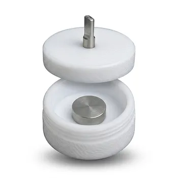
PTFE is highly resistant to strong oxidants, supporting electrolytes, and reactive fluorinated intermediates. This chemical inertness helps prevent the cell body from participating in the degradation chemistry.
PTFE also resists corrosion from aggressive electrolytes and does not readily release metal impurities into solution. That is important when measuring catalyst activity or tracking low concentrations of fluoride and reaction intermediates.
Electrical Insulation Reduces Background Interference
PTFE has strong electrical insulating properties and a wide electrochemical stability range. The cell body therefore does not provide an unintended conductive path or act as a competing redox surface under normal experimental conditions.
This helps reduce background current and leakage-current effects. The result is a cleaner measurement of the current passed through the intended electrode system.
PTFE Minimizes Contamination and Adsorption Concerns
PFOA and its transformation products can be difficult to measure accurately when they adsorb to surfaces or when the apparatus introduces fluorochemical background. A high-purity PTFE cell provides a chemically stable contact surface that helps reduce these concerns.
The cell material should still be cleaned and validated before use. PTFE improves experimental control, but it does not eliminate the need for blanks, recovery checks, and contamination controls.
Precision Machining Stabilizes the Reaction Geometry
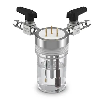
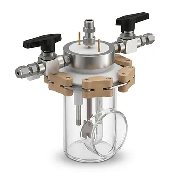
Custom CNC machining allows the cell to match the specific dimensions of the electrodes, reference components, sampling ports, and fluid connections. Exact electrode spacing improves current distribution and makes the experimental configuration repeatable.
A precisely manufactured enclosure can also provide tight electrolyte sealing. This reduces leakage and limits evaporation, both of which can change electrolyte concentration and distort comparisons between experiments.
Enclosed Designs Support Reliable Long Experiments
PFOA degradation studies may involve prolonged electrolysis and reactive intermediates. A sealed PTFE design helps maintain a consistent solution volume and limits exposure to external contamination.
The same stability is valuable when electrolysis is combined with analytical methods such as in-situ spectroscopy. A leak-proof interface prevents electrolyte loss from disrupting measurements or damaging adjacent components.
Understanding the Trade-offs
PFOA Degradation Is Not the Same as Defluorination
A reduction in measured PFOA concentration indicates that the parent compound has been removed or transformed. It does not establish that the carbon-fluorine bonds have been fully broken.
Defluorination is better assessed by measuring released fluoride and, where relevant, identifying intermediate products. Reporting both degradation and defluorination prevents an incomplete picture of treatment performance.
Higher Current Is Not Automatically Better
A greater current density may accelerate conversion, but it can also alter selectivity, energy use, and intermediate formation. It may increase the contribution of side reactions or create conditions that complicate interpretation.
Current density should therefore be optimized together with anode composition, electrolyte, electrode area, and treatment time.
PTFE Does Not Replace Experimental Controls
PTFE reduces chemical and electrical interference, but reliable conclusions still require appropriate controls. These commonly include electrolyte blanks, cell-material blanks, electrode-only controls, and measurements of both PFOA disappearance and fluoride release.
Analytical recovery and background checks are especially important because trace fluorochemical contamination can affect apparent degradation results.
Customization Requires Dimensional and Chemical Validation
A custom cell must be checked for electrode fit, sealing performance, electrical isolation, and compatibility with the selected electrolyte. Poorly designed ports or seals can introduce leaks, evaporation, or unwanted current paths.
The design should also account for sampling, gas release where relevant, cleaning, and safe handling of oxidizing reaction mixtures.
How to Apply This to Your Experiment
The most defensible design treats electrochemical conditions and cell construction as one integrated experimental system.
- If your primary focus is maximum PFOA removal: Optimize the anode material, maintain a controlled current density such as 10 mA/cm², select a compatible supporting electrolyte, and monitor pseudo-first-order degradation over time.
- If your primary focus is mineralization and fluoride release: Measure defluorination independently from PFOA disappearance and track fluoride and transformation products throughout the experiment.
- If your primary focus is reproducibility: Use a precision-machined PTFE cell with fixed electrode spacing, stable sealing, controlled solution volume, and a repeatable electrode layout.
- If your primary focus is analytical accuracy: Use high-purity PTFE, run material and electrolyte blanks, and verify that the cell does not contribute fluorochemical background or metal-ion contamination.
- If your primary focus is mechanistic electrochemistry: Use PTFE’s electrical insulation and chemical inertness to minimize background currents while controlling electrode geometry and operating conditions.
Reliable PFOA electrochemical degradation depends on controlling the chemistry, charge transfer, mass transport, and experimental hardware as a single system.
Summary Table:
| Parameter | Impact on PFOA Degradation | Typical Value / Example |
|---|---|---|
| Anode material | Determines oxidation efficiency | Ti/SnO₂-Sb, Ti/SnO₂-Sb/PbO₂ |
| Current density | Controls driving force | 10 mA/cm² |
| Supporting electrolyte | Enhances conductivity | NaClO₄ |
| Reaction time | Affects conversion extent | 90 minutes |
| Cell geometry | Influences mass transfer | Fixed electrode spacing |
| Kinetics | Enables comparison | Pseudo-first-order |
Elevate your PFOA degradation research with KINTEK's precision-machined PTFE electrochemical cells. Our custom cells provide superior chemical resistance, electrical insulation, and contamination control for accurate, reproducible results. Whether you need standard or bespoke designs, our CNC machining expertise ensures a perfect fit for your electrodes, sampling ports, and fluid connections. Contact us today to optimize your electrochemical experiments and achieve reliable degradation and defluorination data. Get in touch with our specialists to discuss your custom requirements and benefit from our high-purity PTFE/PFA labware and components.
Related Products
- Corrosion Resistant PTFE Electrochemical Cell for New Energy Research Inert Insulating Customizable Lab Reaction Vessel
- Square PTFE Electrochemical Cell for Silicon Wafer Processing and Hydrofluoric Acid Resistance in Semiconductor and New Energy Research
- PTFE Flat Plate Working Electrode Electrochemical Cell for Sheet Samples Corrosion Testing and SEM Sample Preparation
- All PTFE Exchangeable Membrane Electrochemical Cell Dual Chamber Three Electrode Photoelectrochemical Cell for Laboratory Trace Analysis
- Corrosion Resistant PTFE Photoelectrochemical Cell High Purity All PTFE Three Electrode Test Cell with Quartz Window
People Also Ask
- How do custom PTFE electrochemical cells improve the accuracy of stability testing for alkaline catalysts compared to glass cells?
- How does the hydrophobicity of PTFE benefit electrochemical measurements? Enhance Stability and Precision in Your Lab
- What makes PTFE an ideal construction material for custom electrochemical cells and electronic analytical instrumentation housings? Discover superior chemical resistance and electrical insulation
- Why must seawater electrolysis test cells have high corrosion resistance? Protect catalyst stability & data accuracy.
- What are the key steps for structural integrity in molded PTFE lab reaction vessels? Master fine powder processing.