The node-and-fibril structure is the primary basis for selecting ePTFE. Solid PTFE nodes provide mechanical stability, while the fine fibrils connecting them create the porous network that controls permeability, pore size, and particle retention. By adjusting expansion conditions and the resulting internodal distance, manufacturers can tailor ePTFE for customized laboratory apparatus, hydrophobic venting, or high-efficiency filtration membranes while preserving PTFE’s chemical and thermal resistance.
Material selection should match the ePTFE’s internodal distance, fibril orientation, porosity, and mechanical requirements to the intended fluid, pressure, temperature, and retention target. A tighter structure improves fine-particle retention, while a more open structure generally provides greater flow and gas permeability.
How the Node-and-Fibril Structure Works
Nodes Provide the Structural Framework
Nodes are relatively dense regions of PTFE that function as anchor points within the membrane. The fibrils extend between these nodes, distributing mechanical loads across the porous structure.
This arrangement allows ePTFE to retain substantial strength despite containing a high volume of interconnected void space. It is particularly useful in laboratory components that must remain dimensionally stable during handling, pressure changes, or repeated exposure to aggressive chemicals.
Fibrils Create the Porous Network
Fibrils are extremely fine PTFE strands formed when high-molecular-weight PTFE resin is subjected to shear and expansion. They connect adjacent nodes and define the pathways through which gases, vapors, or liquids can move.
Fibril orientation also matters. Stretching can align the fibrils and increase tensile strength, while uniaxial and biaxial expansion produce different structural orientations and mechanical behaviors.
Internodal Distance Controls Functional Performance
The distance between neighboring nodes, known as the internodal distance, is a key indicator of the resulting pore structure. It can typically be engineered from a few microns to tens of microns, depending on the manufacturing process and intended application.
A smaller or more tightly controlled structure is generally suited to finer particle retention and contamination control. A more open structure can support higher gas or fluid flow, but may provide less restrictive separation.
Selecting ePTFE for Filtration Membranes
Match Pore Structure to Retention Requirements
For filtration, the relevant question is not simply whether a membrane is porous. The pore-size distribution must be compatible with the particles, droplets, aerosols, or biological material that must be retained.
A controlled node-and-fibril network can provide precise particle retention while maintaining useful permeability. Selection should therefore consider the target contaminant size, acceptable pressure drop, and required flow rate together.
Balance Permeability and Filtration Efficiency
Increasing openness generally improves permeability, but it can reduce the membrane’s ability to retain smaller particles. Conversely, a tighter structure can improve separation while increasing resistance to flow.
The correct grade is the one that provides sufficient retention without imposing an unacceptable operating pressure or slowing the laboratory process. This balance is especially important in sample preparation, analytical instrumentation, and fluidics systems.
Use Hydrophobicity for Gas and Liquid Separation
ePTFE combines a porous structure with very low surface energy. As a result, it can allow air and vapor to pass while resisting wetting by aqueous liquids under appropriate operating conditions.
This makes it useful for hydrophobic vent filters, pressure-equalization caps, gas sensor vents, and phase-separation barriers. The membrane can help prevent liquid leakage and particulate entry while relieving pressure generated by volatile reagents or chemical reactions.
Consider Mechanical Integrity in the Finished Assembly
The membrane must withstand the pressure differential and handling forces imposed by the apparatus. Fibril orientation, node connectivity, thickness, and support conditions all influence whether the membrane remains stable during use.
A membrane that meets a nominal pore-size target but lacks sufficient mechanical durability may deform, rupture, or lose consistent filtration performance when installed in a custom component.
Selecting ePTFE for Customized Laboratory Apparatus
Define the Operating Environment First
Customized apparatus should be selected around the actual chemical, thermal, and mechanical conditions. ePTFE is valued for its resistance to aggressive solvents and acids, low friction, and thermal stability at elevated temperatures.
However, chemical compatibility alone does not determine suitability. Pressure, flexing, clamping, repeated thermal cycling, and dimensional tolerances can be equally important.
Choose Porosity According to the Component’s Function
A porous ePTFE component intended for gas exchange requires a different structure from one intended for restrictive particle filtration. For example, a reagent-bottle vent may prioritize gas permeability and liquid repellency, while a sample-preparation membrane may prioritize controlled retention.
The node-and-fibril configuration should therefore be specified as a functional requirement rather than treated as a generic material characteristic.
Account for Fibril Orientation
Uniaxial expansion and biaxial expansion produce different orientations within the porous matrix. These differences can affect tensile behavior, dimensional stability, and permeability depending on the direction of applied stress or flow.
For custom-machined or integrated components, the manufacturer should evaluate how the expansion direction will align with pressure loads, bending, clamping, and fluid movement.
Specify Consistency for Woven or Reinforced Components
When ePTFE is used as a fiber or incorporated into a structured support, uniform cross-sectional dimensions are important. Engineered fibers with controlled width and thickness can reduce edge fraying and preserve more consistent porosity during weaving or knitting.
This consistency improves repeatability in flow, mechanical durability, and long-term behavior in chemical or high-temperature environments.
Understanding the Trade-offs
Smaller Pores Can Increase Flow Resistance
Fine pores can improve particle retention, but they also make it more difficult for gases or liquids to pass through. Designing solely for the smallest possible pore size can produce excessive pressure drop or impractical processing times.
The filtration target should be defined by required separation performance, not by pore size alone.
High Porosity Does Not Eliminate Mechanical Constraints
ePTFE can achieve very high porosity while retaining useful strength because the nodes and fibrils form a connected framework. Nevertheless, thin membranes can remain vulnerable to tearing, puncture, unsupported pressure, or damage during assembly.
Support layers, appropriate thickness, and controlled installation may be necessary for demanding laboratory applications.
Hydrophobicity Has Operating Limits
ePTFE’s hydrophobicity helps resist aqueous wetting, but liquid breakthrough can occur when pressure, surface tension, pore structure, contamination, or liquid chemistry changes. Organic solvents may also interact differently with the membrane than water.
Performance claims should therefore be validated using the actual liquid, pressure differential, temperature, and exposure time expected in service.
Manufacturing Consistency Affects Results
Two membranes described by the same nominal pore size may not perform identically if their pore-size distributions, thicknesses, fibril orientations, or support structures differ.
For customized apparatus, qualification should include flow rate, retention, pressure resistance, chemical exposure, and dimensional stability rather than relying only on a material name or nominal specification.
How to Apply This to Your Project
The most reliable selection process connects the microscopic structure to the apparatus-level requirement.
- If your primary focus is fine-particle or contamination control: Choose a tightly controlled ePTFE structure with an internodal distance and pore-size distribution matched to the smallest material that must be retained, then verify the resulting pressure drop.
- If your primary focus is high gas or vapor permeability: Select a more open, hydrophobic ePTFE grade that provides the necessary flow while resisting liquid wetting and particulate ingress.
- If your primary focus is aggressive chemical or high-temperature service: Prioritize ePTFE grades and assemblies with demonstrated resistance under the actual reagents, temperature, pressure, and exposure duration.
- If your primary focus is a custom-machined or integrated laboratory component: Evaluate thickness, fibril orientation, support, clamping, and dimensional stability in addition to nominal porosity.
- If your primary focus is repeatable production: Specify controlled internodal distance, thickness, pore-size distribution, and fiber geometry so that filtration and flow behavior remain consistent between parts.
When the node-and-fibril architecture is treated as a design variable, ePTFE can be selected precisely for the required balance of strength, permeability, chemical resistance, and filtration efficiency.
Summary Table:
| Factor | Low Internodal Distance (Tight) | High Internodal Distance (Open) |
|---|---|---|
| Pore Size | Smaller | Larger |
| Permeability | Lower | Higher |
| Retention | Finer particles | Coarser particles |
| Mechanical Strength | Generally higher (more nodes) | May be lower (fewer nodes) |
| Typical Use | High-efficiency filtration, contamination control | Gas venting, high-flow applications |
Optimize Your ePTFE Selection with KINTEK!
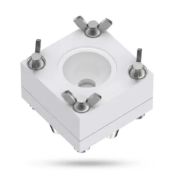
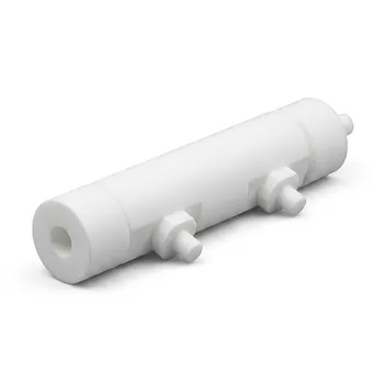
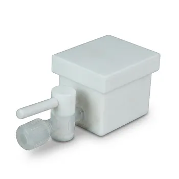
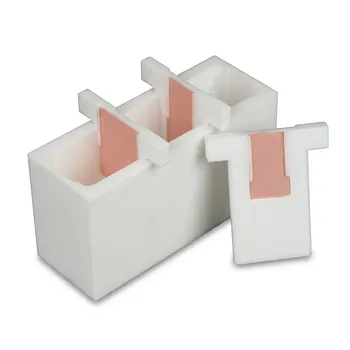
Leverage our expertise in high-performance fluoropolymers. We manufacture custom PTFE and PFA labware, filtration membranes, and fluid handling components. From bespoke filtration membranes to precision-machined apparatus, our porous ePTFE solutions are engineered to your exact internodal distance, porosity, and mechanical requirements. Whether you need tight control for fine-particle retention or open structures for high gas flow, we deliver. Contact us now to discuss your application and benefit from our end-to-end custom CNC machining and high-volume manufacturing capabilities.
Related Products
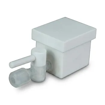
- PTFE Flat Plate Working Electrode Electrochemical Cell for Sheet Samples Corrosion Testing and SEM Sample Preparation
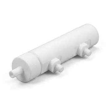
- Custom PTFE Electrolytic Cell Corrosion Resistant Low Background Reaction Vessel with Inlet Outlet Ports
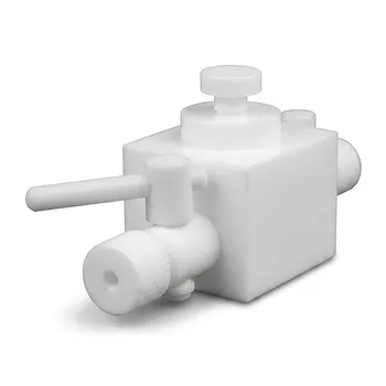
- Custom PTFE Corrosion Resistant Insulating Electrophoresis Reaction Cell with Septum and Valves for Low Background Trace Analysis
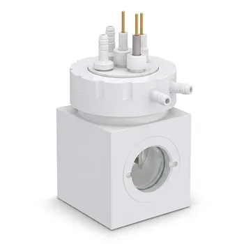
- White PTFE Electrolytic Cell with Movable Slider and Insulated Lid for Fluorine Corrosion Resistance
- Corrosion Resistant PTFE Evaporation Cell Electrophoresis Tank 400ml Flame Retardant Insulated Reaction Vessel Customizable
People Also Ask
- What makes PTFE an ideal construction material for custom electrochemical cells and electronic analytical instrumentation housings? Discover superior chemical resistance and electrical insulation
- Why are high-performance fluoropolymers like PTFE and PFA preferred for electrochemical cells and sensitive analytical instrumentation? Achieve Reliable, Contamination-Free Measurements
- What material properties allow fluoropolymers to withstand extreme heat and corrosion? Discover how PTFE and PFA ensure inertness, stability, and purity for demanding lab applications.
- How does the electroactive β-phase in fluoropolymer battery separators enhance lithium-ion transport, and why are custom electrochemical cells necessary for evaluating these membrane performance characteristics?
- How do sol-gel ceramic-like coatings compare to fluoropolymer materials regarding maximum temperature capability and hardness? Discover the key differences for fluid processing and surface coating applications.