Melting and cooling fundamentally reset virgin PTFE’s structure. Virgin PTFE begins with a crystallinity above 90% and a melting point near 340°C (644°F), but its extremely high melt viscosity prevents ordinary melt flow and limits crystal reorganization. After sintering, melting, and cooling, the polymer typically recrystallizes to less than 70% crystallinity, with an apparent melting point near 328°C (622°F), even when cooled slowly. The exact result depends on cooling rate, part thickness, and the component’s complete thermal history.
The first melting cycle erases much of virgin PTFE’s original crystalline order. Cooling then rebuilds a new, less perfect crystalline structure; slower cooling generally increases crystallinity and dimensional stability, while rapid cooling increases toughness and flexibility but also residual stress and shrinkage risk.
Why Virgin PTFE Changes During Fabrication
Extremely High Melt Viscosity Limits Reorganization
Virgin PTFE has an exceptionally high molecular weight and a melt viscosity of approximately 10^10 to 10^12 P. Above its melting transition, it forms a stiff, highly viscous gel rather than flowing like conventional thermoplastics.
This behavior suppresses normal crystal growth during the original manufacturing process. As a result, virgin PTFE can retain an unusually high crystalline fraction, commonly exceeding 90%, with a melting point near 340°C.
Sintering Creates a New Polymer Structure
PTFE labware is generally made by compacting powder into a preform, heating it above the melting point, and allowing the particles to coalesce during sintering. The resulting matrix is dense and homogeneous, but it no longer has the same crystalline arrangement as the starting powder.
The melting step partially or substantially erases the original crystalline structure. The subsequent cooling cycle determines how the chains reorganize as the material passes through its crystallization or freeze range, approximately 320°C to 325°C.
How Cooling Alters Crystallinity
Slow Cooling Produces More Ordered Material
During slow cooling, PTFE chains have more time to fold and pack into ordered, accordion-like crystalline structures. This generally produces larger crystallites, higher crystallinity, greater density, and lower internal stress.
Reported values illustrate the effect: cooling at approximately 0.1°C/min can produce roughly 62% crystallinity, whereas rapid quenching in ice water can reduce crystallinity to approximately 45%. These values describe processed PTFE after melting and should not be confused with the greater than 90% crystallinity of virgin, unmelted material.
Rapid Cooling Freezes in a Less Ordered Structure
Rapid cooling restricts chain movement before complete crystalline organization can occur. The result is a larger amorphous fraction and finer crystalline domains.
Lower crystallinity generally makes PTFE more flexible, tougher, and somewhat more transparent. However, rapid cooling can also produce greater inhomogeneous strain, residual thermal stress, and local differences between the outer surface and the interior of a thick component.
Thickness Makes the Cooling Problem More Difficult
PTFE has low thermal conductivity, so the outside of a thick-walled vessel or digestion tube can cool substantially faster than its core. This temperature gradient causes different regions to crystallize at different times and rates.
For large or heavy-walled labware, controlled cooling, such as approximately 8°C to 15°C per hour down to about 250°C, helps the core and outer wall approach thermal equilibrium. This reduces warping, internal cracking, and dimensional variation.
Why the Melting Point Drops After the First Cycle
Recrystallized PTFE Has Less Perfect Crystals
After virgin PTFE has been melted and cooled, its new crystalline structure is usually less complete and less ordered than the original structure. The lower crystalline fraction and smaller or less perfect crystallites require less thermal energy to disrupt.
Consequently, a later heating cycle commonly shows an apparent melting point near 328°C (622°F) rather than the approximately 340°C (644°F) associated with virgin PTFE.
Melting Point Reflects Thermal History
The reported melting point is not only a fixed material constant; it also reflects the specimen’s processing history and measurement history. Cooling rate, maximum temperature, hold time, part thickness, and the number of previous heating cycles can all influence the observed melting behavior.
A slower cooling cycle generally increases the amount and perfection of recrystallized material, which can shift the melting response upward relative to rapidly cooled PTFE. It does not normally restore the original virgin condition completely, because the first melt has already changed the polymer’s structural history.
What This Means for Fluoropolymer Labware
Dimensional Stability Improves With Controlled Crystallinity
Higher crystallinity increases specific gravity, stiffness, hardness, opacity, and resistance to chemical permeation. These characteristics are valuable in precision labware that must retain its shape under heat, pressure, or prolonged chemical exposure.
Controlled slow cooling is therefore important for components such as reaction vessels, digestion tubes, fluid fittings, and custom-machined parts where dimensional accuracy and creep resistance matter.
Toughness and Flexibility Require a Different Balance
Lower crystallinity increases the amorphous fraction, which can improve flexibility and impact tolerance. This may be useful where the part must withstand handling, flexing, or mechanical shock.
The trade-off is reduced stiffness and potentially greater dimensional change under load or temperature. Material selection and cooling conditions should therefore be matched to the part’s actual service requirements rather than optimized for crystallinity alone.
Machining Must Account for the Processed State
CNC machining does not restore virgin PTFE crystallinity. It shapes the material after sintering, so machining allowances and tolerances must account for thermal shrinkage, residual stress, and the final crystallinity distribution.
For thick or complex parts, uneven cooling can leave internal stresses that later relax during machining or use. This can cause delayed warping or loss of dimensional accuracy even when the initial machined dimensions are correct.
Understanding the Trade-offs
Slow Cooling Is Not Always the Best Choice
Slow cooling tends to improve order, density, stiffness, and chemical barrier performance, but it lengthens production time. It can also produce a stiffer part that is less tolerant of mechanical deformation.
The appropriate cooling rate depends on whether the priority is dimensional stability, chemical permeation resistance, toughness, flexibility, or manufacturing throughput.
Rapid Quenching Can Create Hidden Defects
Quenching can lower crystallinity and increase flexibility, but it also increases thermal gradients and residual stress. In thick-walled PTFE, the surface may solidify while the core remains hot and continues shrinking.
That mismatch can lead to warping, internal cracking, void-related defects, or dimensional drift during later machining and service.
Crystallinity Data Must Be Interpreted Carefully
Values such as 62% crystallinity for slow cooling and 45% for quenching are useful process comparisons, not universal specifications for every PTFE grade and geometry. Measurements depend on the material, sample preparation, thermal cycle, and analytical method.
The key engineering principle is the direction of the effect: cooling rate changes crystallinity, and crystallinity changes density, stiffness, permeability, stress, and dimensional behavior.
Making the Right Choice for Your Goal
Choose the thermal cycle according to the labware’s operating demands:
- If your primary focus is dimensional stability: Use a controlled, relatively slow cooling cycle that allows thermal equilibration through the wall and promotes higher crystallinity with lower residual stress.
- If your primary focus is chemical permeation resistance: Favor higher crystallinity and density, while verifying that the resulting stiffness and shrinkage remain acceptable.
- If your primary focus is toughness and flexibility: A faster, controlled cooling cycle can retain more amorphous material, but thick parts still require stress management.
- If your primary focus is precision machining: Characterize the post-sintered material rather than relying on virgin PTFE data, and allow for thermal shrinkage and delayed stress relaxation.
- If your primary focus is repeatable production: Control the heating peak, hold time, cooling rate, part thickness, and furnace uniformity as one integrated thermal process.
Understanding PTFE’s thermal history allows manufacturers to predict its crystallinity, melting behavior, and dimensional performance instead of treating virgin and post-sintered material as equivalent.
Summary Table:
| Factor | Virgin PTFE | Processed PTFE (After Melting/Cooling) |
|---|---|---|
| Crystallinity | >90% | <70% (e.g., ~62% slow cool, ~45% quench) |
| Melting Point | ~340°C (644°F) | ~328°C (622°F) |
| Structure | Highly ordered | Less ordered, smaller crystallites |
| Impact | Baseline properties | Affects stiffness, permeability, toughness |
Optimize your PTFE labware fabrication with KINTEK's expertise in high-performance fluoropolymers. From custom CNC machining to standard labware, our solutions ensure precise thermal control for superior crystallinity and dimensional stability. Contact us today to discuss your specific requirements!
Related Products
- Custom PTFE Filtration System Acid Resistant High Purity Semiconductor Grade Chemical Processing Filter
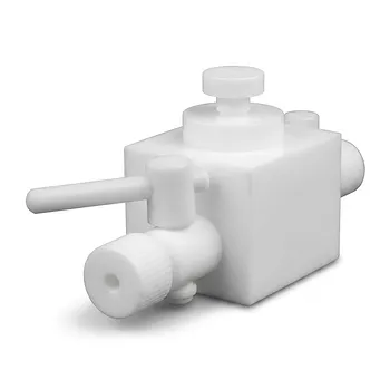
- High Corrosion Resistant PTFE Faucet Polytetrafluoroethylene Valve for Chemical Storage Drums and Fluid Transfer Systems Customizable Industrial Grade
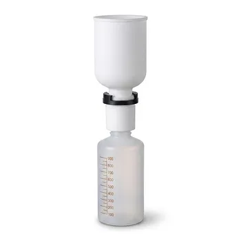
- PTFE PFA Vacuum Filtration System Corrosion Resistant Customizable Shatterproof Laboratory Device
- PTFE Corrosion Resistant Filter with PFA Valve Connections and Integrated Sieve Plate
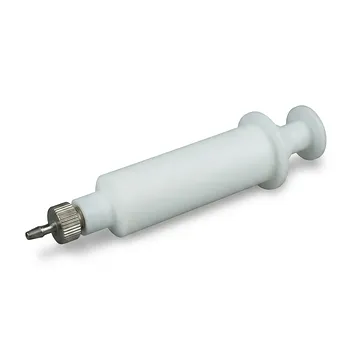
- High Temperature Chemical Resistant 50ml PTFE Syringe Customized Teflon Injector with Threaded Seal for Trace Analysis
People Also Ask
- What makes PTFE filtration systems advantageous for industrial and scientific use? Unmatched Chemical & Thermal Stability
- What steps are involved in selecting the proper PTFE filter? A 4-Step Guide to Optimal Filtration
- What sizes and pore options are available for PTFE filters? Choose the Right Filter for Your Application
- How does the hydrophobicity of PTFE filters benefit their use? Ensure Uninterrupted Gas Flow and Solvent Filtration
- What temperature resistance do PTFE filters offer? Unmatched Thermal Stability from -200°C to +260°C