PTFE’s room-temperature phase transitions can shift component dimensions enough to compromise tight fits, seal integrity, and volumetric accuracy. The most important change occurs between approximately 19°C and 30°C, where molecular disorder produces a specific-volume increase of up to 1.8%. Because this is a volumetric change, the corresponding linear dimensional change is not automatically 1.8%; for an idealized isotropic part it would be roughly 0.6% per dimension, while actual results depend on geometry, crystallinity, machining direction, residual stress, and thermal history.
Custom-machined PTFE components should be machined, inspected, and calibrated at a controlled reference temperature, commonly 25°C. Measurements taken on opposite sides of the 19°C or 30°C transitions may describe materially different dimensions, even when the part has not been mechanically altered.
Why PTFE Changes Near Room Temperature
The transition near 19°C
Below approximately 19°C, PTFE has a predominantly triclinic crystalline structure. Near 19°C, the polymer chains partially untwist and the crystal structure changes toward a hexagonal arrangement.
This is a first-order crystalline phase transition, meaning the material can undergo a relatively abrupt change in structure and volume rather than responding only through smooth thermal expansion.
The transition near 30°C
Between approximately 19°C and 30°C, PTFE chain segments become progressively more disordered. At around 30°C, the ordered hexagonal structure disappears into a more disordered crystalline state.
The associated structural changes contribute to a substantial increase in specific volume across this temperature range. The primary reference identifies the overall change as up to 1.8%, a significant amount for precision components.
Why ordinary thermal-expansion assumptions are insufficient
A conventional thermal-expansion calculation assumes a relatively smooth and predictable change with temperature. PTFE’s transitions near common laboratory temperatures introduce additional structural effects that can be sharper and more history-dependent.
For that reason, a generic coefficient of thermal expansion alone may not predict the dimensional behavior of a tight-tolerance PTFE fitting or seal accurately across the 19°C to 30°C range.
How the Volume Change Affects Machined Dimensions
Linear dimensions change by less than the volume percentage
A 1.8% increase in volume does not mean that every length, diameter, or thickness increases by 1.8%. If expansion were uniform in all directions, the approximate linear change would be:
[ \frac{\Delta L}{L} \approx \frac{1}{3}\frac{\Delta V}{V} ]
For a 1.8% volumetric increase, this gives an approximate linear change of 0.6%. This is a useful conceptual estimate, not a universal design value.
PTFE parts may deviate from this simplified behavior because of anisotropic structure, machining orientation, filler content, porosity, geometry, and residual stress.
Small percentages become large tolerance errors
A 0.6% linear change is substantial in precision work. A 100 mm dimension could theoretically shift by about 0.6 mm under a uniform linear interpretation, while a 10 mm feature could shift by about 0.06 mm.
Those changes are much larger than the tolerances commonly specified for precision sealing surfaces, valve interfaces, metering features, and fitted laboratory components.
Internal and external features respond differently in use
A bore, shaft-like feature, groove, or sealing land may change dimension in a way that alters clearance or compression. The resulting functional change depends on whether the component is an internal feature, an external feature, or part of a constrained assembly.
A dimensional change that appears modest on a drawing can therefore produce a measurable change in leak rate, insertion force, valve operation, or seal compression.
Effects on Common Laboratory Components
Fluid fittings and threaded connections
PTFE fittings depend on controlled interference, thread engagement, and sealing deformation. Temperature-driven dimensional changes can alter the fit between mating threads or the compression of a sealing surface.
If a fitting is machined or inspected below 19°C but assembled at 20°C to 25°C, its dimensions may not correspond to the dimensions used for process qualification.
Sealing components
Seal rings, gaskets, valve seats, and custom sealing elements are especially sensitive because performance depends on both geometry and material deformation.
A temperature-related change in groove fill, radial interference, or axial compression can cause either excessive assembly stress or insufficient contact pressure. The result may be premature wear, difficult assembly, or leakage.
Volumetric labware and metering components
PTFE bodies used for fluid measurement, dosing, or electrochemical apparatus can experience changes in cavity dimensions and wall geometry. These changes may affect calibrated volume even when the component remains visually stable.
For high-accuracy applications, calibration temperature must be treated as part of the measurement specification rather than as an incidental laboratory condition.
Valve bodies and moving interfaces
PTFE’s dimensional movement can change clearances between plugs, stems, seats, and bores. A valve that operates freely at one temperature may become tighter, less responsive, or more prone to leakage at another.
This is particularly important for small clearances, low-force actuators, and assemblies combining PTFE with materials that have different thermal responses.
How Machining and Inspection Should Be Controlled
Establish one reference temperature
Machining, final inspection, and calibration should use a defined and stable reference temperature, commonly 25°C. The part, measuring equipment, and relevant fixtures should be allowed to reach thermal equilibrium before critical measurements are taken.
A nominal “room temperature” is not sufficiently precise when the working environment can move across the 19°C transition.
Avoid measuring across a transition
A component should not be dimensionally accepted based on measurements taken while its temperature is moving through approximately 19°C or 30°C. The material may be changing structurally during the measurement process.
Temperature should be recorded with the inspection results, especially for tight-tolerance parts and parts whose dimensions determine sealing or calibrated volume.
Condition stock before machining
PTFE stock should be stabilized at the intended machining environment before critical operations. This reduces the risk that the material changes dimension after being cut, inspected, or assembled.
The same principle applies to post-machining conditioning: a newly machined component may require a controlled hold period before final acceptance if residual stress relaxation or temperature equilibration can affect the specification.
Specify tolerances with functional temperature in mind
The drawing should distinguish between the measurement temperature and the operating temperature range. A part that meets its dimensional tolerance at 25°C may still require functional verification at the temperatures where sealing, metering, or motion must remain reliable.
For critical interfaces, the design review should evaluate the full assembly rather than judging PTFE dimensions in isolation.
Understanding the Trade-offs
Tight tolerances may not solve temperature sensitivity
Reducing the machining tolerance does not eliminate PTFE’s temperature-dependent dimensional behavior. It can produce a highly accurate part at the inspection temperature that still fails to perform across the operating range.
The correct response is to control temperature, define functional limits, and account for material behavior in the design.
The 1.8% value is not a universal dimensional correction
The reported 1.8% value describes a change in specific volume, not a guaranteed increase in every part dimension. Applying 1.8% directly to a diameter or length would generally overstate the dimensional correction.
Actual behavior should be established for the specific PTFE grade, geometry, machining process, and temperature history when the tolerance or performance requirement is critical.
PTFE may continue to move after machining
PTFE is susceptible to creep, stress relaxation, and deformation under load. Temperature-related phase changes add another source of dimensional variation.
A component may therefore fail to maintain its initial measurement even when it was machined correctly. Long-term dimensional stability and assembly loading must be considered alongside the room-temperature transitions.
Mixed-material assemblies increase the risk
PTFE is often assembled with metals, glass, ceramics, or other polymers. These materials have different thermal expansion and stiffness characteristics.
The interface may therefore experience relative movement, changing compression or clearance more than a PTFE-only dimensional calculation would suggest.
Making the Right Choice for Your Goal
Temperature control and functional verification should be treated as part of the component specification, not as optional inspection practices.
- If your primary focus is dimensional precision: Machine, condition, inspect, and calibrate the PTFE component at a documented reference temperature, typically 25°C, while recording the actual part temperature.
- If your primary focus is leak-tight sealing: Evaluate interference, groove fill, compression, and mating dimensions across the full operating temperature range rather than relying on room-temperature inspection alone.
- If your primary focus is volumetric accuracy: Calibrate the actual fluid cavity at the intended reference and operating temperatures, because volumetric changes are not equivalent to a simple linear size correction.
- If your primary focus is repeatable production: Control stock conditioning, machining environment, inspection temperature, and post-machining stabilization so that every part is evaluated under the same thermal conditions.
- If your primary focus is assembly reliability: Design clearances and fits around the behavior of the complete material combination, including PTFE, mating components, loads, and temperature changes.
By controlling temperature and separating volumetric phase-transition effects from ordinary linear expansion, engineers can specify PTFE tolerances that remain meaningful in actual laboratory service.
Summary Table:
| Phase Transition | Temperature Range | Impact on Dimensions | Critical for |
|---|---|---|---|
| First-order crystalline transition | ~19°C | Abrupt structural change, volumetric increase | Dimensional stability, tight fits |
| Progressive disorder | 19°C–30°C | Up to 1.8% specific volume increase (≈0.6% linear) | Sealing, volumetric accuracy |
| Ordinary thermal expansion | >30°C | Smaller, smoother dimensional changes | General lab use |
Ensure your PTFE components meet rigorous tolerances despite temperature-induced phase transitions. KINTEK's precision machining and expert guidance help you achieve reliable performance. Contact us today to discuss your custom PTFE labware needs and benefit from our dedicated support and high-quality materials. Get in touch.
Related Products
- Custom PTFE Filtration System Acid Resistant High Purity Semiconductor Grade Chemical Processing Filter
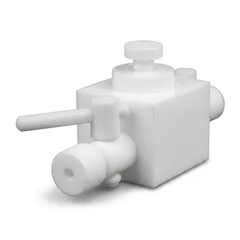
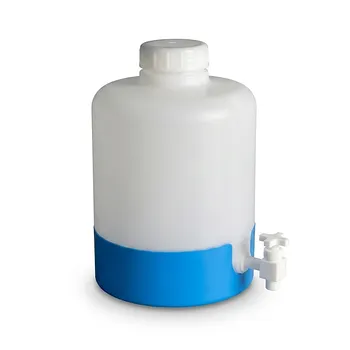
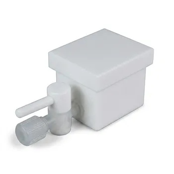
- High Corrosion Resistant PTFE Faucet Polytetrafluoroethylene Valve for Chemical Storage Drums and Fluid Transfer Systems Customizable Industrial Grade
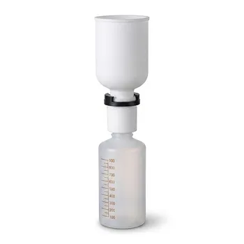
- PTFE PFA Vacuum Filtration System Corrosion Resistant Customizable Shatterproof Laboratory Device
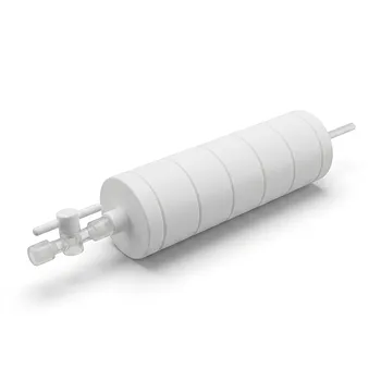
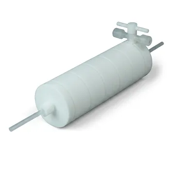
- PTFE Corrosion Resistant Filter with PFA Valve Connections and Integrated Sieve Plate
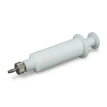
- High Temperature Chemical Resistant 50ml PTFE Syringe Customized Teflon Injector with Threaded Seal for Trace Analysis
People Also Ask
- What makes PTFE filtration systems advantageous for industrial and scientific use? Unmatched Chemical & Thermal Stability
- What sizes and pore options are available for PTFE filters? Choose the Right Filter for Your Application
- What steps are involved in selecting the proper PTFE filter? A 4-Step Guide to Optimal Filtration
- What temperature resistance do PTFE filters offer? Unmatched Thermal Stability from -200°C to +260°C
- How does the hydrophobicity of PTFE filters benefit their use? Ensure Uninterrupted Gas Flow and Solvent Filtration