Die wall angle and guide tube clearance are two of the main controls governing PTFE paste flow and surface quality. A cone angle of approximately 20° generally suits thin coatings and fine tubing, while 30° is typically better for thicker extrudates. The guide tube tip clearance should normally remain within 25–50 µm; excessive clearance can cause drag, cracking, or paste back-extrusion, while insufficient clearance restricts flow and sharply increases pressure.
Core takeaway: Smooth PTFE extrusion depends on controlled material flow, not simply on a polished die. The correct cone angle, tightly controlled guide clearance, and mirror-finished internal surfaces work together to minimize friction, pressure instability, fibrillation defects, and dimensional variation.
How Die Wall Angle Affects PTFE Surface Smoothness
The angle controls paste compression
The die cone transitions the PTFE paste from a larger passage into the smaller final profile. Its angle determines how rapidly the paste is compressed and how the PTFE particles deform and fibrillate during passage through the die.
A poorly selected angle can create uneven flow, localized pressure changes, and excessive deformation. These conditions may appear on the extrudate as roughness, tearing, cracking, or nonuniform wall thickness.
Why 20° suits thin profiles
A cone angle of approximately 20° is generally recommended for thin PTFE coatings, fine tubing, and fine conductor insulation.
The more gradual transition helps maintain controlled paste movement through the high-reduction section. This is particularly important when a small change in flow behavior can produce a visible surface defect or disturb the coating’s concentricity.
Why 30° suits thicker extrudates
A cone angle of approximately 30° is commonly used for thicker coatings and heavier-wall profiles.
Thicker extrudates require a different balance between compression, flow resistance, and material throughput. The steeper transition can provide the required forming behavior without imposing the same flow constraints associated with an unsuitable geometry for that application.
These values should be treated as application-specific starting points rather than universal rules. Product dimensions, reduction ratio, paste formulation, extrusion speed, and pressure must also be considered.
How Guide Tube Clearance Controls Surface Integrity
Clearance governs flow around the core
The guide tube or guide tip positions the conductor, mandrel, or core relative to the die. Its clearance controls how easily paste moves around that central element and therefore affects coating thickness, concentricity, strip force, and surface tension.
For many PTFE paste extrusion applications, the tip clearance is maintained within approximately 25–50 µm. At this scale, even a small machining error can materially change the flow balance.
Excessive clearance creates instability
If the clearance is too large, the paste can move unevenly around the guide tip. Increased drag and tension may pull or stretch the forming PTFE layer, making it more vulnerable to cracking.
Excessive clearance can also permit paste to flow backward into the guide tube. This back-extrusion disrupts material delivery, contaminates the guide path, and can contribute to dimensional variation or surface defects.
Insufficient clearance raises pressure
If the clearance is too small, the passage becomes restrictive. Paste flow is impeded, extrusion pressure rises, and the process becomes more sensitive to small changes in alignment or material condition.
The resulting pressure spike can damage surface quality and may reduce the desired tightness or uniformity of the PTFE layer around the core. A clearance that is mechanically “tight” is therefore not automatically better.
Why Internal Surface Finish Matters
Roughness becomes a flow disturbance
The die cone and die land directly contact the moving paste. Any machining marks, pits, burrs, or microscopic irregularities increase friction and disturb the material as it enters and travels through the final forming region.
These disturbances become more significant at high extrusion pressures and speeds. They can produce tearing, micro-cracks, rough textures such as sharkskin, and inconsistent surface appearance.
Mirror polishing reduces friction
The internal die surfaces should be precision-machined and polished to approximately 0.1 µm Ra or finer, depending on the specified process requirement.
A mirror-like finish reduces shear friction and prevents surface irregularities in the tool from being transferred to the PTFE. It also supports more stable pressure, smoother fibrillation, and more uniform wall formation.
The die land is especially critical
The die land is the final sizing region, so its geometry and finish have a direct influence on the finished surface and dimensions.
A polished cone alone is insufficient if the land remains rough, damaged, or improperly aligned. Both regions must be treated as functional flow surfaces and inspected accordingly.
Why Precision Machining Is Essential
Small errors have large process effects
PTFE paste extrusion often involves narrow clearances, high reduction ratios, and substantial extrusion pressures. A small deviation in cone geometry, guide position, land diameter, or surface finish can therefore produce a disproportionate change in pressure and flow.
This is why visual inspection alone is inadequate. The component may appear acceptable while still causing unstable extrusion or inconsistent product dimensions.
Concentricity protects wall uniformity
The guide tube, core pin, and die must remain accurately aligned. Misalignment changes the local clearance around the core, causing one side of the product to receive more paste than the other.
The result can be eccentric tubing, uneven insulation thickness, localized thinning, and variable mechanical performance. Precision machining and careful assembly are required to maintain concentricity.
CNC machining supports repeatability
High-precision custom CNC machining can produce the required cone, land, guide, and bore dimensions consistently across production components.
However, machining capability must be paired with appropriate polishing, deburring, dimensional inspection, and surface-roughness verification. CNC machining by itself does not guarantee the required mirror finish or functional alignment.
Understanding the Trade-offs
A steeper angle is not automatically better
A larger cone angle may support thicker profiles, but using it for a fine coating can create a less favorable compression and flow pattern. Conversely, a shallow angle selected without regard to the required throughput or wall thickness may increase flow resistance.
The correct angle is the one that matches the product geometry and process conditions—not simply the angle that produces the lowest apparent pressure.
Tighter clearance is not always safer
Reducing guide clearance may appear to improve dimensional control, but excessive restriction raises pressure and can destabilize the process.
The practical target is a controlled clearance range, typically 25–50 µm, with enough space for stable paste flow but not so much that drag, back-extrusion, or sheath tension becomes excessive.
Surface finish cannot compensate for poor geometry
A highly polished die cannot correct an incorrect cone angle, excessive guide clearance, or misalignment. Likewise, precise geometry cannot overcome rough internal surfaces.
Surface smoothness is therefore a system result produced by geometry, clearance, alignment, and finish working together.
How to Apply This to Your Project
Use the following priorities when specifying or troubleshooting a PTFE paste extrusion die:
- If your primary focus is thin coatings or fine tubing: Start with an approximately 20° cone angle, then validate pressure, wall thickness, and surface quality under actual operating conditions.
- If your primary focus is thicker coatings or heavier-wall profiles: An approximately 30° cone angle is generally the more suitable starting point.
- If your primary focus is preventing surface defects: Specify polished cone and land surfaces at approximately 0.1 µm Ra or finer, and verify the finish rather than relying only on a visual “mirror” appearance.
- If your primary focus is stable coating thickness: Maintain guide tube tip clearance within the 25–50 µm range and verify concentricity between the guide, core, and die.
- If your primary focus is repeatable production: Use precision custom machining followed by inspection of critical dimensions, clearance, alignment, burrs, and surface roughness.
When die geometry and guide clearance are machined and verified as a coordinated system, PTFE extrusion becomes more stable, predictable, and capable of producing consistently smooth surfaces.
Summary Table:
| Parameter | Recommended Range/Value | Impact on Surface Smoothness |
|---|---|---|
| Cone Angle (thin profiles) | ~20° | Gradual compression reduces defects for thin coatings and fine tubing. |
| Cone Angle (thick profiles) | ~30° | Suitable for thicker extrudates; balances flow and forming. |
| Guide Tube Clearance | 25–50 µm | Prevents drag, cracking, and back-extrusion; avoids pressure spikes. |
| Surface Finish (Ra) | ≤0.1 µm | Mirror finish minimizes friction and surface irregularities. |
| Concentricity | Precision aligned | Ensures uniform wall thickness and reduces eccentricity. |
Achieve flawless PTFE extrusion with precision-machined components from KINTEK. Our custom PTFE/PFA dies and guide tubes are CNC-machined to exacting tolerances, with mirror-polished surfaces (Ra ≤0.1 µm) to ensure smooth, defect-free products. Whether you need standard labware or complex custom dies, we deliver reliability and repeatability. Contact us today to optimize your extrusion process and enhance product quality.
Related Products
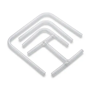
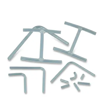
- High Purity PFA Coiled Tubing Custom PTFE Machining PFA Welding and Precision Bending Solutions
- High Performance PFA Coiled Spring Tubing and Custom PTFE Fabrication Services with Welded Fittings and Precision Bent Components
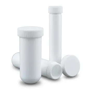
- Custom PTFE Digestion Vessel Sample Vial Straight Wall Test Tube High Temperature Low Background
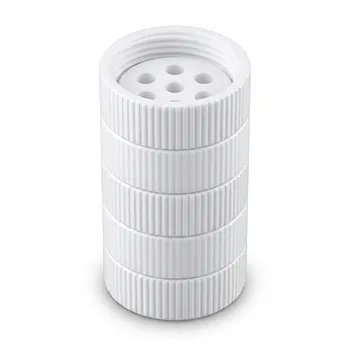
- High Temperature PTFE Reaction Sieve with Customizable Layers and Precision Pore Sizes for Threaded Sample Separation Devices
- High Purity PTFE Digestion Tubes and Custom Centrifuge Tubes 100ml for Trace Analysis and Chemical Digestion
People Also Ask
- How has the elimination of ammonium perfluorooctanoate impacted the manufacturing and safety profile of fluoropolymer products? Key changes and what they mean for you
- What are the technical advantages of high-precision PFA tubing in MXene production? Maximize Purity and Yield.
- PTFE vs PFA: What are the key thermal and processing differences for lab apparatus?
- Why are high-performance fluoropolymers uniquely suited for demanding chemical processing and laboratory applications requiring high thermal and chemical resistance? Discover Their Unmatched Benefits for Your Most Challenging Environments.
- How does interfacial segment migration in fluorinated polymer systems impact surface functionality and chemical barrier performance? Key insights for high-purity fluid handling