Sintered porous PTFE is used because it combines an inert fluorinated surface with a porous structure that can support fluoride-promoted CTFE dimerization. In reported systems, porous PTFE—used alone or with sodium or potassium fluoride—supports conversion of chlorotrifluoroethylene (CTFE) to 4,4-dichlorohexafluoro-1-butene at approximately 300–450°C, with reported dimer yields above 90%.
The key distinction is between PTFE as a catalyst-support matrix and PTFE as laboratory hardware. Porous PTFE may be useful in a validated reaction configuration, but ordinary PTFE tubing, fittings, seals, and vessels should not automatically be treated as suitable for continuous exposure to 300–450°C.
Why Porous PTFE Is Used in CTFE Dimerization
It provides a high-area support structure
Sintering creates an interconnected porous matrix that can distribute reactants through the catalyst bed rather than limiting contact to a smooth external surface.
That structure can also retain or disperse sodium fluoride or potassium fluoride, helping create a more uniform reactive environment.
It avoids unwanted metal surfaces
Fluorinated monomers and intermediates can be highly sensitive to surface chemistry. Conventional metallic reactor surfaces may introduce contamination or provide unintended sites for decomposition, oligomerization, or other side reactions.
A fluoropolymer support minimizes those effects by presenting a chemically inert, nonmetallic environment. This is particularly valuable when product selectivity depends on controlling surface-mediated reactions.
It resists aggressive fluorochemical chemistry
PTFE has exceptional resistance to many halogenated and fluorinated compounds. Its carbon–fluorine-rich structure helps prevent dissolution, swelling, and chemical attack that would affect many conventional organic polymers.
That resistance is a major reason porous PTFE is attractive in fluorochemical processing, provided its temperature, pressure, and mechanical limits are separately verified.
It can support high reported dimer yields
The combination of porous contact, fluoride functionality, and low surface contamination is associated with reported CTFE dimer yields exceeding 90% under specified high-temperature conditions.
Those results should be treated as process-specific, not as a guarantee for every porous PTFE grade, pore structure, catalyst loading, or reactor design.
What the Reaction Environment Demands
Temperature changes the materials decision
The cited reaction range of 300–450°C is far above the normal service range of many commercial PTFE components. PTFE may soften, creep, lose mechanical strength, or decompose depending on temperature, exposure time, oxygen level, pressure, and the presence of reactive species.
Therefore, “chemically compatible with CTFE” does not mean “mechanically suitable at the reaction temperature.”
The reactor must be designed as a pressure system
CTFE is a volatile, hazardous monomer, and heating it can increase vapor pressure and accelerate unwanted reactions. The reactor, closures, lines, and relief system must be rated for the maximum credible temperature and pressure, not merely the intended operating point.
Pressure relief, containment, remote operation, and controlled vent handling are essential design features.
Thermal gradients matter
A hot reactor connected to cool tubing creates thermal expansion, condensation, and stress-management problems. Local hot spots can also change reaction selectivity or accelerate polymer and fluoropolymer degradation.
The design should account for temperature uniformity, heat-up and cool-down rates, expansion allowances, and the temperature of every wetted component.
Vital Lab Hardware Considerations
Use PTFE and PFA selectively
Custom-machined PTFE or PFA tubing, fittings, and vessels can be valuable for cooler upstream and downstream sections, where chemical resistance and low contamination are more important than high-temperature structural strength.
They should not be assumed suitable for the 300–450°C reaction zone. PFA generally offers fabrication and flexibility advantages, but it also has temperature limitations and is not a substitute for a high-temperature reactor alloy or ceramic.
Select the reactor body independently
The main hot-zone reactor may require a material specifically qualified for the temperature, pressure, and fluorochemical environment. Depending on the process, this could involve a suitable nickel-based alloy, high-temperature alloy, or ceramic construction.
The choice must consider corrosion, permeation, catalytic activity, weld integrity, embrittlement, and contamination. “Metal-free” is not always the safest or most mechanically realistic requirement; the correct goal is a validated, low-contamination, corrosion-resistant system.
Treat seals and fittings as critical components
Seals often fail before the reactor body. Elastomers can swell, decompose, permeate CTFE, or lose compression at elevated temperature.
Use seals and valve seats that are specifically rated for the actual temperature, pressure, and fluorochemical exposure. Minimize dead legs, threaded crevices, and trapped volumes where monomer or reactive residues could accumulate.
Control contamination and surface condition
All wetted parts should be cleaned, dried, and inspected before use. Residual oils, machining debris, moisture, and metal particles can affect fluoride chemistry or generate side reactions.
If PTFE is machined, remove loose particles and verify that the finished surface does not shed material into valves, filters, or the catalyst bed.
Understanding the Trade-offs
Porous PTFE is not automatically a conventional catalyst
PTFE is primarily valuable here as a support matrix and inert processing surface. The actual catalytic behavior may depend strongly on incorporated sodium or potassium fluoride, pore accessibility, residence time, and the conditioning history of the bed.
A porous part that is chemically compatible may still have inadequate pore size, permeability, strength, or catalyst distribution.
Chemical inertness does not eliminate thermal degradation
PTFE and related fluoropolymers are highly resistant to chemical attack, but high temperatures can cause creep, loss of strength, and decomposition. At severe temperatures, decomposition products may themselves be hazardous and corrosive.
For that reason, supplier temperature ratings, long-duration aging data, and reaction-specific compatibility testing are more reliable than a generic “PTFE is inert” assumption.
Avoid overreliance on fluoropolymer fluid paths
Fluoropolymer tubing is excellent for many cold or moderately heated transfer duties, but flexible tubing is particularly vulnerable to softening, permeation, deformation, and pressure failure.
Keep polymeric components outside the hot zone whenever practical, and use short, well-supported transition sections between the reactor and cooler equipment.
How to Apply This to Your Project
The appropriate design depends on whether porous PTFE is being used as a catalyst support, a fluid-transfer material, or both.
- If your primary focus is catalytic performance: Use sintered porous PTFE as a validated support or matrix for the fluoride-promoted CTFE reaction, and characterize pore structure, catalyst distribution, permeability, and long-term stability rather than relying on material identity alone.
- If your primary focus is hardware compatibility: Separate the hot reaction zone from cooler fluid-transfer sections, qualify every wetted component for temperature and pressure, and do not use standard PTFE or PFA hardware at 300–450°C without documented validation.
- If your primary focus is product selectivity: Minimize uncontrolled metal contact, contamination, hot spots, and residence-time variation, while verifying that the reactor material itself does not promote competing surface reactions.
- If your primary focus is laboratory safety: Design for toxic and reactive monomer containment, pressure relief, remote monitoring, inerting where appropriate, controlled off-gas treatment, and a formal review of thermal-decomposition hazards.
A successful CTFE dimerization setup treats porous PTFE as a specialized catalytic-support material—not as a universal high-temperature construction material—and validates the entire reactor system as one integrated pressure, thermal, and chemical design.
Summary Table:
| Aspect | Porous PTFE Role | Lab Hardware Consideration |
|---|---|---|
| Temperature | Supports reaction up to 300–450°C | Use high-temperature alloys/ceramics for reactor; not standard PTFE/PFA |
| Chemical Resistance | Inert to fluorochemicals | Ensure seals/fittings rated for temp/pressure and chemical exposure |
| Surface Area | Provides high-area matrix for catalyst | Validate pore structure, permeability, and catalyst distribution |
| Contamination | Minimizes metal surface reactions | Clean all wetted parts to avoid contamination and side reactions |
| Mechanical Strength | Limited at high temp; creep/decomposition risk | Design for pressure, thermal expansion, and avoid overreliance on polymers |
| Reaction Yield | Supports >90% dimer yields in specific processes | Optimize residence time, temperature uniformity, and reactor design |
Ready to optimize your CTFE dimerization setup? At KINTEK, we specialize in high-performance PTFE and PFA labware, including custom CNC-machined parts for bespoke reaction systems. Our products ensure chemical inertness, low contamination, and precise fabrication for your specific needs. From fluid transfer components to specialized reaction vessels, we provide solutions that balance material limitations with your process requirements. Contact us today to discuss how we can enhance your reactor design and achieve superior yields with reliable hardware. Get in touch with our experts!
Related Products
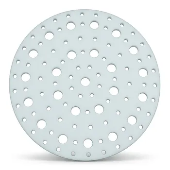
- High Temperature Resistant Insulating TFM Separator and Ultra Clean Laboratory PTFE Baffle Plate with Customizable Pore Size and Hole Configuration
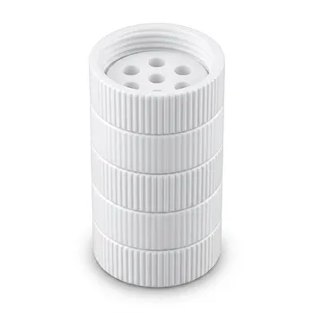
- High Temperature PTFE Reaction Sieve with Customizable Layers and Precision Pore Sizes for Threaded Sample Separation Devices
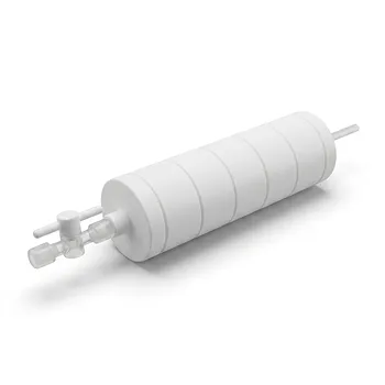
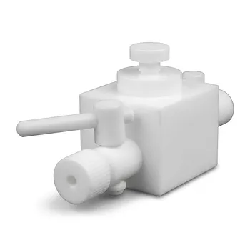
- PTFE Corrosion Resistant Filter with PFA Valve Connections and Integrated Sieve Plate
- Custom PTFE Filtration System Acid Resistant High Purity Semiconductor Grade Chemical Processing Filter
- High Purity PTFE Filter with PFA Valve Connections and Integrated Sieve Plate for Corrosive Fluid Processing
People Also Ask
- What are the limitations of pure PTFE in high temperature applications? Understanding the 200°C Ceiling
- Are Teflon parts capable of withstanding high temperatures? Understanding the 260°C Limit for Performance
- What future advancements are expected in temperature-resistant PTFE seals? Discover Smarter, Tougher Sealing Solutions
- What is porous PTFE used for? Advanced Filtration for Harsh Chemical & High-Temp Environments
- What are the benefits of porous PTFE? Unlock Superior Filtration and Chemical Resistance