PTFE sintering requires strict control of polymer temperature, exhaust capture, and cooling rate. Keep the PTFE itself from exceeding approximately 380°C for extended periods, because degradation accelerates rapidly above this level. Use dedicated local exhaust ventilation to capture hazardous decomposition products, and apply controlled, slow cooling when higher crystallinity, dimensional stability, and more predictable dielectric performance are required.
Core takeaway: Do not treat oven setpoint as the only thermal limit—the actual PTFE temperature and residence time control degradation risk. Use the lowest effective sintering profile, effective source capture, and a cooling schedule matched to the part’s thickness and required crystallinity.
Thermal Limits During PTFE Sintering
Control the actual polymer temperature
PTFE must be heated above its melting transition, approximately 342°C, to allow particles or extruded material to coalesce. However, the polymer should not remain above approximately 380°C, where thermal decomposition accelerates significantly.
Some processes use oven setpoints in the 370–420°C range, and certain equipment may operate at still higher nominal temperatures to compensate for heat transfer or reduce melt viscosity. These values do not remove the requirement to keep the local polymer temperature and exposure time within safe limits.
Use the lowest effective temperature
The process should use the lowest temperature and shortest residence time that achieve complete consolidation, void closure, and the required surface quality. Excessive temperature can damage the PTFE and may also impair the substrate in coated or laminated products.
For PTFE dispersion coatings, a staged profile is appropriate:
- Drying: approximately 30–100°C to remove moisture.
- Baking: approximately 200–315°C to decompose and volatilize surfactants.
- Sintering: approximately 370–420°C to melt and coalesce PTFE particles.
Extending the baking-zone residence time is generally preferable to raising the sintering temperature when the objective is complete surfactant removal.
Prevent overheating with equipment controls
Sintering ovens should include temperature limit switches, independent over-temperature protection, and reliable temperature measurement near the product. The control system should identify hot spots rather than relying only on the oven-air temperature.
Before opening an oven, allow the equipment and product to cool sufficiently to reduce both burn hazards and the release of residual fumes.
Exhaust and Worker-Safety Requirements
Capture emissions at the source
Heating PTFE near sintering temperatures can generate hazardous fluorinated decomposition products, including hydrofluoric acid, carbonyl fluoride, tetrafluoroethylene, and perfluoroisobutylene, as well as fine particulates.
The oven should therefore have dedicated exhaust ventilation, with Local Exhaust Ventilation positioned as close as practical to the emission source. The supplementary guidance specifies a minimum capture velocity of approximately 0.5 m/s for source capture.
Do not rely on general room ventilation
General room air changes are not an adequate substitute for source capture at the oven, loading area, or discharge point. Exhaust should continuously remove contaminated air before it enters the operator’s breathing zone.
The exhaust system should be designed and maintained for the actual process, including decomposition products from PTFE, surfactants, additives, and substrate coatings.
Control exposure during abnormal events
Over-temperature events, equipment failures, and opening a hot oven can produce concentrated emissions. Establish procedures for alarms, emergency shutdown, evacuation, and inspection before restarting the process.
Personnel should use appropriate protective equipment based on the documented exposure assessment. Respiratory protection or supplied-air equipment may be required for potential high-concentration exposures; respirators should not be used as a replacement for effective engineering controls.
Cooling Controls for Crystallinity
Cooling determines the final structure
As molten PTFE cools through approximately 320–325°C, polymer chains begin packing into ordered crystalline regions. The cooling rate therefore influences crystallinity, density, stiffness, dimensional behavior, and residual stress.
Natural air cooling commonly produces crystallinity around 50–60%, while rapid cooling can reduce crystallinity to approximately 45–50%, depending on grade, geometry, and the exact cooling cycle.
Use slow cooling for thick or heavy parts
Thick-walled PTFE has low thermal conductivity and undergoes substantial volumetric shrinkage during solidification. If the surface cools much faster than the core, the resulting temperature and shrinkage gradients can cause warping, internal stress, or cracking.
For large parts, controlled cooling of roughly 8–15°C per hour down to about 250°C can help maintain thermal equilibrium between the exterior and core. The appropriate rate must still be validated for the part’s wall thickness and geometry.
Use quenching only for a defined property target
Cold air or water-bath quenching lowers crystallinity and can increase flexibility in some designs. However, it may also reduce stiffness, alter dimensional behavior, and create higher residual stresses in thick sections.
Quenching should therefore be used only when the lower-crystallinity structure is intentional and the resulting mechanical and electrical properties have been verified.
How Crystallinity Affects Dielectric Performance
Maintain a consistent cooling history
Changes in crystallinity alter PTFE’s physical structure and can affect dielectric strength, dimensional stability, flexibility, and mechanical behavior. For thicker insulation, inconsistent cooling can produce property variations between the surface and the core.
A repeatable cooling profile is more important than simply choosing the fastest or slowest possible cooling rate. Record product temperature, not only oven temperature, when developing a qualified cycle.
Do not design at the maximum breakdown value
PTFE may exhibit short-term dielectric breakdown resistance of up to approximately 24 kV/mm under defined test conditions. This is a maximum test value, not a recommended continuous operating stress.
Actual test and operating voltages should remain below the material’s maximum demonstrated limit, with appropriate allowance for thickness variation, defects, temperature, geometry, aging, and manufacturing variability.
Verify finished parts, not only the process
For electrical insulation, qualify the finished product after its complete thermal history. Testing should account for the actual crystallinity, wall thickness, cooling profile, void content, and dimensional tolerances.
A process that produces acceptable dielectric results in thin coupons may not produce the same performance in a thick or complex component.
Understanding the Trade-offs
Higher crystallinity versus flexibility
Slower cooling generally increases crystallinity, density, stiffness, hardness, and dimensional stability. The trade-off is that the product may be less flexible than a rapidly quenched equivalent.
Lower crystallinity from rapid cooling can improve flexibility but may change dielectric strength and mechanical performance, particularly in thicker sections.
Throughput versus thermal safety
Higher oven temperatures or shorter cycles may improve throughput, but they reduce the margin against local overheating and degradation. Raising the setpoint is not an appropriate substitute for correcting inadequate heat transfer, poor loading, or insufficient baking time.
Cooling speed versus residual stress
Rapid cooling reduces cycle time but increases the risk of thermal gradients and residual stress. This risk is greatest in heavy, thick-walled, or geometrically complex products.
Nominal temperature versus product temperature
A major process-control mistake is treating the oven setpoint as the material limit. The product may be cooler than the oven during heating and hotter internally during cooling, so multiple product-temperature measurements may be necessary for cycle validation.
Making the Right Choice for Your Goal
Use the process objective to select the thermal and cooling strategy:
- If your primary focus is maximum crystallinity and dimensional stability: Use complete consolidation followed by controlled, slow cooling—especially through approximately 320–325°C and for thick sections.
- If your primary focus is flexibility: Consider a validated faster-cooling cycle, while confirming that the resulting lower crystallinity does not compromise dielectric or dimensional requirements.
- If your primary focus is dielectric reliability: Maintain a repeatable thermal history, avoid overheating and void formation, and operate well below the measured short-term breakdown limit of approximately 24 kV/mm.
- If your primary focus is worker safety: Install source-capture LEV, target approximately 0.5 m/s capture velocity where applicable, use over-temperature interlocks, and keep personnel away from hot-oven emissions.
- If your primary focus is production throughput: Optimize drying, baking residence time, loading, and heat transfer before increasing the sintering temperature.
A qualified PTFE sintering process balances polymer temperature, exposure time, exhaust capture, and cooling rate rather than optimizing any one variable in isolation.
Summary Table:
| Parameter | Requirement |
|---|---|
| Max PTFE temp | ~380°C (avoid prolonged exposure) |
| Sintering temp range | 370–420°C (oven setpoint) |
| Cooling for high crystallinity | Slow cooling: 8–15°C/hr down to ~250°C |
| Exhaust capture velocity | ~0.5 m/s at source |
| Dielectric breakdown limit | Up to ~24 kV/mm (short-term test) |
Ensure your PTFE sintering process meets safety and quality standards. Contact KINTEK today for high-performance PTFE/PFA labware and custom solutions tailored to your needs. Contact us to discuss your requirements.
Related Products
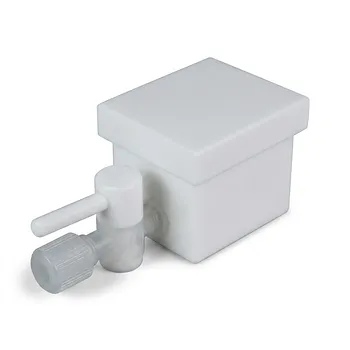
- Custom PTFE Laboratory Apparatus Corrosion Resistant Low Background Reaction Cells Precision CNC Fabrication
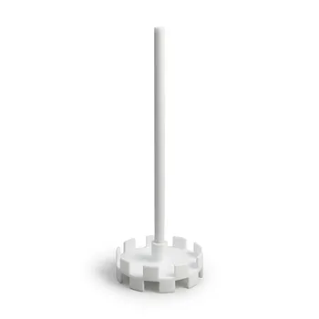
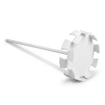
- Corrosion Resistant PTFE Stirring Impeller and Customizable Polytetrafluoroethylene Dispersion Disk
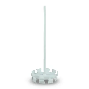
- Corrosion Resistant PTFE Dispersing Disc and High Temperature Propeller Stirring Paddle for Laboratory Chemical Mixing
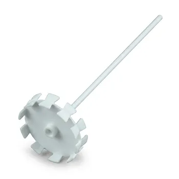
- Corrosion Resistant PTFE Stirring Paddle and Customizable Toothed Dispersion Disk for Chemical Pharmaceutical Mixing
- High Purity PTFE Square Membrane Cutter Equipartition Device for Trace Analysis and Disease Control Centers Clean Non Stick No Leaching
People Also Ask
- How does PTFE's melting behavior affect custom lab apparatus? Key insights for manufacturing.
- What are the primary fabrication methods for PTFE laboratory apparatus? Expert Insights into Fluoropolymer Engineering
- What is the chemical compatibility range for PTFE laboratory apparatus? Explore Near-Universal Chemical Resistance.
- What are the primary chemical resistance properties of PTFE laboratory apparatus? Unmatched Purity and Inertness
- Why use PTFE or PFA for modified Cu-MOF synthesis? Ensure High Purity and Exceptional Chemical Stability