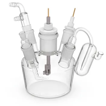
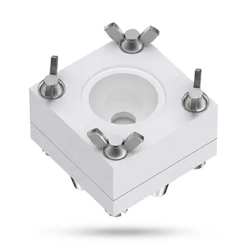
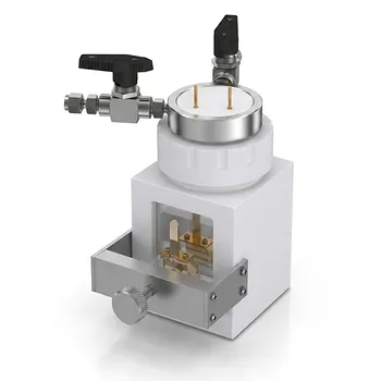
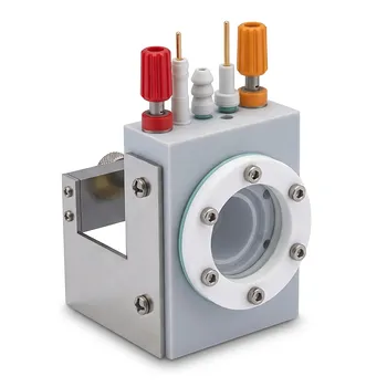
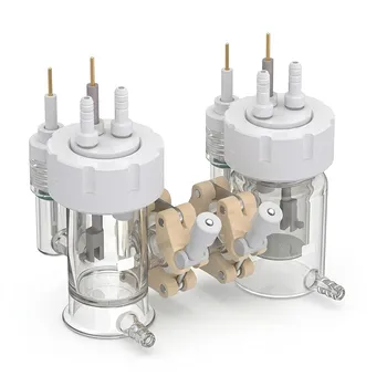
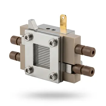
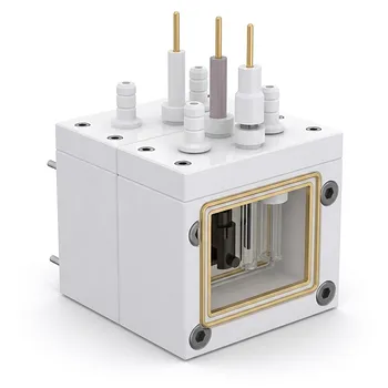
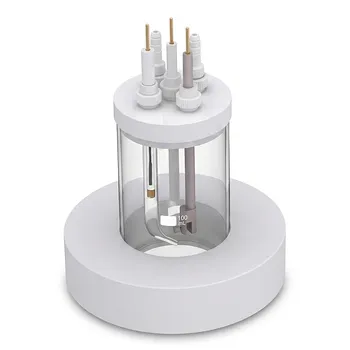
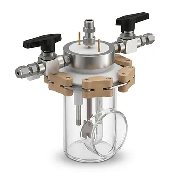
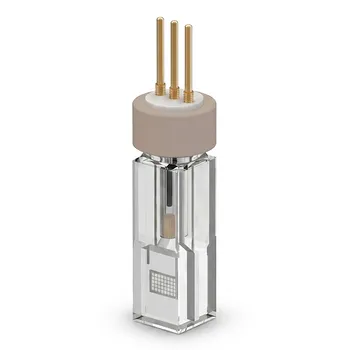
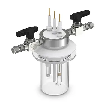
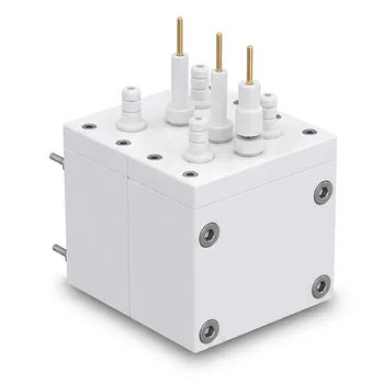
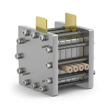
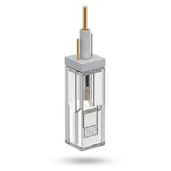
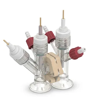
The reliability of cyclic voltammetry (CV) and spectroelectrochemistry (SEC) depends on more than the polymer itself. Custom electrochemical cells must provide stable three-electrode contact, a controlled electrolyte environment, and consistent optical access while researchers account for reference-electrode solvation, electrode kinetics, baseline quality, and counter-ion transport. CV can estimate redox potentials and electronic energy levels, but SEC is often necessary to connect those electrochemical changes with the polymer’s optical and charge-compensation behavior.
A custom cell should be treated as part of the measurement, not merely as a container. Reliable characterization requires control over electrode geometry, electrolyte contact, potential referencing, current interpretation, optical path, and ion movement through the polymer film.
Designing the Cell Around the Measurement
Maintain a Stable Three-Electrode Configuration
A controlled cell should accommodate a working electrode, reference electrode, and counter electrode with stable positioning throughout the experiment. The arrangement determines how consistently the polymer is polarized and how reproducibly current is measured.
The reference electrode should remain close enough to the working electrode to provide a stable potential measurement, while the counter electrode must support the applied current without introducing avoidable limitations.
Control the Electrolyte Environment
The cell must maintain reliable contact between the supporting electrolyte and the electrode surface. Electrolyte composition, concentration, volume, and wetting affect ion availability, conductivity, and the polymer’s redox response.
A supporting electrolyte such as 0.1 M KCl may be appropriate for some systems, but it should be selected according to the polymer, electrode materials, solvent, and intended application.
Secure the Working Electrode
Physical movement of a screen-printed or otherwise small working electrode can change the effective contact area and optical alignment during measurement. The custom cell should therefore hold the electrode securely and reproducibly.
Stable positioning is particularly important when comparing charge-transfer resistance, specific capacitance, peak currents, or optical spectra across multiple measurements.
Interpreting Cyclic Voltammetry Correctly
Separate Thermodynamics From Electrode Kinetics
Measured oxidation and reduction onset potentials contain both thermodynamic information and electrode kinetic information. An onset is therefore not a purely intrinsic energy value for the polymer.
The observed potential can be influenced by electron-transfer rates, polymer-film morphology, electrode contact, electrolyte transport, and the criterion used to identify the onset.
Use a Consistent Potential Reference
Potentials may be reported relative to reference electrodes such as Ag/AgCl or SCE, or relative to an external standard such as Fc/Fc+. These choices must be stated clearly because changing the reference changes the numerical potential scale.
Comparisons between experiments require consistent reference conventions and appropriate consideration of how the reference standard behaves in the selected solvent and electrolyte.
Account for Solvation Effects
Reference standards and redox species can experience solvation effects that alter their effective work functions or redox energies. Ignoring these effects can shift calculated HOMO and LUMO estimates.
This is one reason electrochemical energy levels should be treated as measurement-dependent estimates rather than direct substitutes for optical or spectroscopic values.
Define the Polymer Configuration
CV behavior differs depending on whether the redox-active material is measured in solution, deposited as a thin film, or grafted directly onto the working electrode. The configuration affects diffusion, film resistance, ion transport, and the fraction of material electrically addressed.
For thin films, film thickness, coverage, adhesion, and contact with the electrode should be kept consistent between samples.
Avoiding Misleading Energy-Level and Bandgap Estimates
Treat CV Bandgaps as Operational Values
Researchers often use onset oxidation and reduction potentials to estimate HOMO and LUMO levels and then derive an electrochemical bandgap. However, the result reflects the measurement conditions and analysis method as well as the polymer.
Measured CV bandgaps can differ from optical bandgaps by 0.3 eV or more, particularly when baselines, reference corrections, and onset assignments are not handled consistently.
Establish the Baseline Before Extrapolation
An unideal baseline can make the onset appear earlier or later than it actually is. Background current, capacitive current, electrolyte response, and electrode effects should be considered when identifying the relevant faradaic feature.
The baseline treatment should be applied consistently across samples and documented sufficiently for another researcher to reproduce the analysis.
Standardize Onset and Peak Analysis
Linear extrapolation of a rising current feature is inherently sensitive to the selected region and baseline. Subjective choices can produce substantial variation in calculated onset potentials.
Use a defined analysis procedure for selecting peak or onset regions, fitting baselines, and reporting uncertainty. Do not compare values obtained from visibly different extrapolation methods as though they were equivalent.
Using Spectroelectrochemistry to See the Redox Process
Link Potential to Optical Response
SEC combines controlled electrochemical polarization with in situ optical spectroscopy. It shows how electronic absorption changes as the polymer is oxidized or reduced.
This provides information that CV alone cannot supply, including the appearance, disappearance, or evolution of absorption bands associated with different redox states.
Evaluate Electrochromic Function
For electrochromic polymers, SEC can track optical modulation as a function of applied potential. The cell must therefore provide a stable and unobstructed optical path through the polymer-coated electrode and electrolyte.
Optical alignment should remain fixed during potential sweeps and between electrochemical and spectroscopic measurements. Otherwise, apparent spectral changes may reflect geometry or scattering rather than polymer redox chemistry.
Monitor Emission When Relevant
SEC configurations can also be used to observe light emission during electrochemical operation when the material and optical setup support it. Emission measurements require careful control of background light, electrode placement, and the collection geometry.
The relevant question is not only whether a spectral feature changes, but whether that change tracks the applied potential and the electrochemical response reproducibly.
Observe Counter-Ion Mass Transfer
Redox switching in a polymer commonly requires charge compensation by ion movement. SEC can help monitor the consequences of counter-ion diffusion and migration through the polymer film and surrounding electrolyte.
Ion transport may control switching speed, spectral uniformity, hysteresis, and the reversibility of the redox response. A custom cell should allow sufficient electrolyte access without compromising film adhesion or optical measurement.
Connecting Electrochemical and Optical Results
Compare Different Measures of the Electronic Structure
CV-derived energy levels and optical absorption data answer related but different questions. Electrochemical measurements probe charge transfer at defined potentials, whereas optical measurements reflect allowed electronic transitions and the state of the material under illumination or polarization.
A difference between an electrochemical bandgap and an optical bandgap is not automatically an experimental failure. It should prompt examination of reference corrections, onset analysis, kinetics, morphology, and the distinction between the two measurements.
Use Potential-Resolved Spectra
Collecting spectra at controlled potentials allows researchers to associate specific optical changes with oxidation or reduction events. This is more informative than recording a single spectrum before and after electrochemical cycling.
Potential increments, hold times, scan conditions, and the direction of polarization should be consistent when comparing samples or redox cycles.
Correlate Current With Spectral Change
The electrochemical current indicates charge transfer, while the optical response indicates how the polymer’s electronic structure changes. Agreement between these signals strengthens the interpretation that the observed spectral evolution is electrochemically driven.
A mismatch may indicate slow ion transport, incomplete switching, capacitive contributions, uneven film coverage, optical scattering, or electrode instability.
Understanding the Trade-offs
Customization Improves Control but Adds Variables
A custom cell can improve electrode fixation, electrolyte contact, optical access, and experimental repeatability. However, every design choice can introduce new variables, including altered diffusion distances, nonuniform illumination, dead volume, leakage, or changes in electrode geometry.
The cell should therefore be validated with repeat measurements and, where practical, against a known or established configuration.
Higher Signal Can Increase Distortion
Increasing polymer loading or film thickness may produce stronger optical absorption and larger currents. It can also make ion transport less uniform, increase film resistance, and cause only part of the film to switch effectively.
A strong signal is not necessarily a more representative signal. The measured response should be interpreted alongside reversibility, scan-rate behavior, spectral uniformity, and physical film condition.
Reference Stability Does Not Remove Kinetic Effects
A stable reference electrode improves potential control, but it does not eliminate kinetic limitations at the working electrode. Slow electron transfer, uncompensated resistance, and ion migration can still shift or broaden CV features.
Potential values should therefore be compared only when cell geometry, electrolyte, electrode preparation, scan conditions, and analysis procedures are controlled.
Optical Access Can Conflict With Electrochemical Geometry
The best optical path may require a different electrode arrangement from the one that provides the most uniform electrochemical current distribution. Window placement, electrode spacing, and film orientation should be selected together rather than optimized independently.
This trade-off is especially important when the polymer film must be viewed through the electrolyte or when the working electrode is screen-printed.
Making the Right Choice for Your Goal
The most defensible workflow combines controlled cell construction with explicit electrochemical and optical analysis criteria.
- If your primary focus is redox potentials and energy-level estimates: Use a stable three-electrode cell, state the reference system clearly, account for solvation effects, and apply a consistent baseline and onset-extrapolation method.
- If your primary focus is electrochromic switching: Use SEC to track potential-dependent absorption while maintaining fixed optical alignment, electrolyte contact, and film coverage.
- If your primary focus is ion transport: Design the cell for reproducible electrolyte access and interpret spectral and current changes together to distinguish counter-ion diffusion and migration from purely electronic effects.
- If your primary focus is reproducibility: Secure the working electrode, standardize cell geometry and electrolyte conditions, and document electrode preparation, scan parameters, reference corrections, and data-analysis procedures.
- If your primary focus is comparing electrochemical and optical bandgaps: Treat the values as complementary measurements and investigate baseline, kinetic, solvation, morphology, and onset-analysis differences before drawing conclusions.
A well-designed custom cell turns CV and SEC from isolated measurements into complementary evidence about the polymer’s redox chemistry, electronic structure, and ion-coupled behavior.
Summary Table:
| Factor | Key Consideration |
|---|---|
| Three-electrode configuration | Stable positioning of working, reference, and counter electrodes. |
| Electrolyte environment | Composition, concentration, and wetting for reliable ion availability. |
| Working electrode security | Reproducible contact area and optical alignment. |
| Potential reference | Consistent use of Ag/AgCl, SCE, or Fc/Fc+ with stated conventions. |
| Solvation effects | Adjust for reference standards in non-aqueous solvents. |
| Baseline analysis | Establish consistent baseline before extrapolating onsets. |
| Onset/peak analysis | Standardize extrapolation region and method. |
| Optical path | Fixed alignment for SEC to avoid scattering artifacts. |
| Ion transport | Ensure electrolyte access for counter-ion movement. |
| Film configuration | Control thickness, adhesion, and coverage. |
| Data interpretation | Treat CV and SEC as complementary; compare with optical bandgaps carefully. |
Ready to enhance your redox polymer characterization?
At KINTEK, we specialize in high-performance fluoropolymer solutions tailored for electrochemical research. Our custom PTFE/PFA electrochemical cells are engineered to meet your precise requirements, ensuring stable electrode positioning, reliable electrolyte control, and excellent optical access. Whether you need standard components or bespoke designs, our end-to-end CNC machining capabilities deliver quality and repeatability.
Why choose KINTEK?
- Precision: Custom cell geometries for optimal electrochemical and optical performance.
- Reliability: High-purity PTFE and PFA materials for chemical compatibility and low contamination.
- Expertise: Support for complex setups, including spectroelectrochemistry and microwave digestion.
- Customization: From prototype to high-volume orders, we accommodate your unique needs.
Contact us today to discuss your electrochemical cell requirements and elevate your research.
Related Products
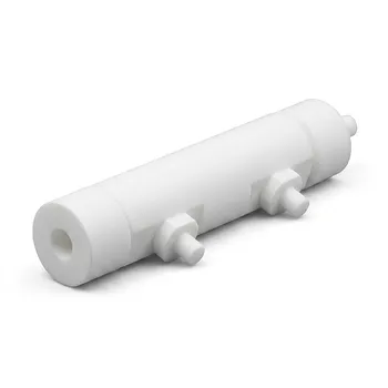
- Custom PTFE Electrolytic Cell Corrosion Resistant Low Background Reaction Vessel with Inlet Outlet Ports
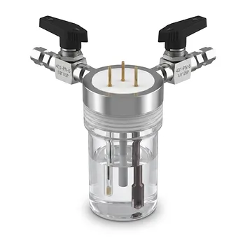
- Straight Five Port Hermetic Electrochemical Cell with Internal Plug In Design and PTFE Lid
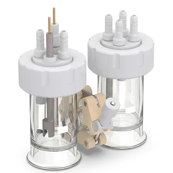
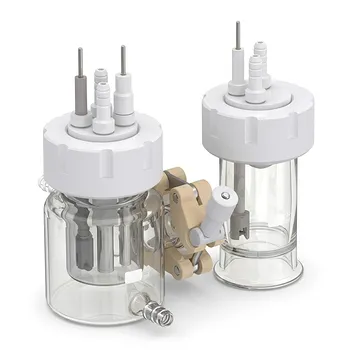
- H Type Replaceable Membrane Electrochemical Cell for Three Electrode System Jacketed Single Layer Gas Purging
- H Type Replaceable Membrane Electrochemical Cell with Sampling Port for Gas Liquid Phase Reactions
- Conventional Five Port Electrochemical Cell Borosilicate Glass Jacketed Three Electrode System
People Also Ask
- Why are high-purity PTFE or PFA reaction vessels recommended for the synthesis of PANI-TiC hybrid materials? - Guide
- Ion Activation Reaction Vessel Requirements: Why PTFE is Critical for Membrane Performance
- Why are fluoroplastic (PTFE) reaction vessels recommended for Methylene Blue (MB) adsorption kinetic experiments?
- What reaction vessel and fluid handling considerations are necessary for living cationic polymerization of fluorinated monomers involving Lewis acid catalysts? Key design and safety tips
- Why is a PTFE reaction vessel required for Ti3C2Tx MXene synthesis? Ensure Safe HF Etching & High Purity