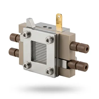
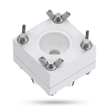
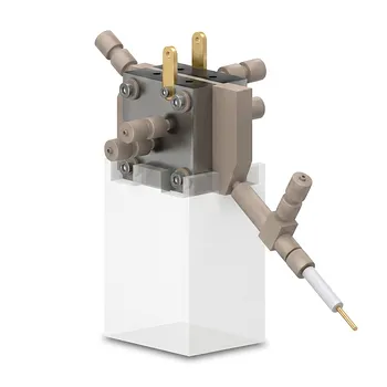
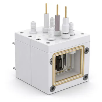
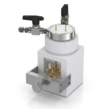
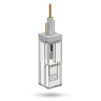
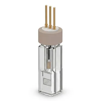
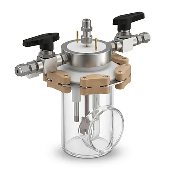
Electrochemical cell systems evaluate PFOA destruction by combining controlled anodic oxidation with precise fluorine and parent-compound measurements. A PFOA-containing electrolyte is placed in a cell fitted with an oxidation-resistant anode, such as Ti/SnO₂–Sb, Ti/SnO₂–Sb/PbO₂, or Ti/SnO₂–Sb/MnO₂. By applying a constant current density—commonly around 10 mA/cm²—researchers track both PFOA disappearance and fluoride release during electrolysis, often under pseudo-first-order kinetics.
The central requirement is to distinguish degradation from true defluorination. A reduction in PFOA concentration shows that the parent molecule is disappearing, while fluoride recovery and fluorine mass balance indicate whether its strong C–F bonds have actually been broken.
How the Electrochemical Cell Is Configured
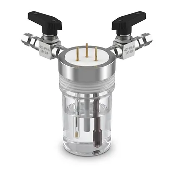
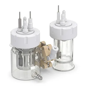
The cell establishes a controlled reaction environment
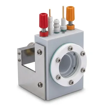
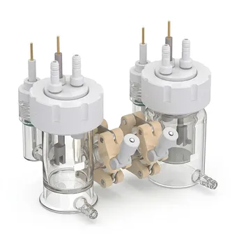
The system contains an aqueous PFOA solution, a supporting electrolyte such as NaClO₄, an anode, and usually a counter-electrode. The power supply imposes a defined current density so that experiments can be compared across electrode materials and operating conditions.
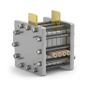
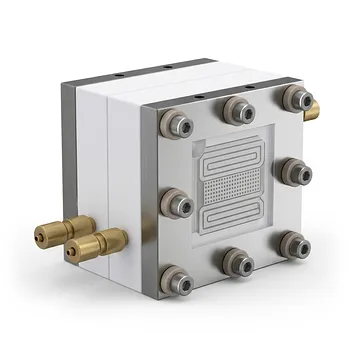
The cell geometry controls electrode spacing, exposed electrode area, mixing, solution volume, and sampling. These parameters influence current distribution and mass transfer, so they must remain consistent when comparing anodes.
The anode drives oxidative decomposition
The anode is the principal site of PFOA oxidation. Electrode materials such as Ti/SnO₂–Sb, Ti/SnO₂–Sb/PbO₂, and Ti/SnO₂–Sb/MnO₂ provide different surface properties and oxidation environments.
PFOA may be attacked at or near the anode through direct electron-transfer processes and reactive oxidizing species generated during electrolysis. The resulting reactions progressively shorten the perfluorinated carbon chain and can ultimately release fluoride ions.
The supporting electrolyte carries current
A supporting electrolyte such as NaClO₄ improves solution conductivity and helps maintain a controlled electrochemical environment. It allows the applied current to be delivered efficiently without making the target compound itself the primary charge carrier.
The electrolyte must be selected carefully because it can affect conductivity, reaction pathways, analytical background, and compatibility with the cell materials.
How Researchers Quantify PFOA Degradation
Parent-compound removal measures degradation
Samples are collected at defined electrolysis times and analyzed for residual PFOA. The degradation efficiency is commonly calculated as:
[ \text{Degradation efficiency} = \left(1-\frac{C_t}{C_0}\right)\times100% ]
where (C_0) is the initial PFOA concentration and (C_t) is the concentration at time (t).
Reported systems can achieve degradation efficiencies above 90% within approximately 90 minutes under suitable electrode and operating conditions.
Kinetic analysis compares reaction rates
PFOA disappearance is often approximated using a pseudo-first-order model:
[ \ln\left(\frac{C_0}{C_t}\right)=k_{\text{obs}}t ]
Here, (k_{\text{obs}}) is the observed rate constant. A linear relationship between (\ln(C_0/C_t)) and time indicates whether this simplified model reasonably describes the experiment.
The model is useful for comparing anodes and operating conditions, but it does not by itself prove complete mineralization or complete fluorine removal.
Fluoride release measures defluorination
Defluorination is evaluated by measuring fluoride ions released into the solution, typically using an appropriate fluoride-specific analytical method. The measured fluoride concentration is compared with the theoretical fluorine content initially present in PFOA.
A simplified defluorination calculation is:
[ \text{Defluorination} = \frac{\text{fluoride released}}{\text{theoretical fluoride from degraded PFOA}} \times100% ]
Under suitable conditions, reported defluorination can reach up to approximately 77% within 90 minutes. This value is distinct from the parent-compound degradation percentage.
Why Degradation and Defluorination Must Be Separated
PFOA disappearance does not prove mineralization
PFOA can be converted into shorter-chain perfluorinated intermediates or other fluorinated products. Consequently, a high PFOA removal percentage may coexist with incomplete C–F bond cleavage.
A credible evaluation therefore measures both residual PFOA and released fluoride, and ideally also investigates intermediate products and total fluorine recovery.
Fluoride release confirms C–F bond cleavage
The key objective in defluorination studies is not merely to destroy the PFOA structure but to release its fluorine as inorganic fluoride. This provides stronger evidence that the persistent perfluorinated framework is being dismantled.
Researchers should account for fluoride present in the initial solution, analytical blanks, sampling losses, and any possible interaction with cell materials when interpreting the result.
Why Fluoropolymer Cell Construction Matters
PTFE and PFA reduce experimental interference
High-purity PTFE or PFA cell bodies, lids, tubing, and fittings are well suited to aggressive electrochemical studies. These fluoropolymers resist strong electrolyte solutions, oxidizing conditions, and reactive fluorinated intermediates.
They also help reduce concerns about background ion leaching, analyte adsorption, and contamination that could compromise low-level measurements.
Cell materials protect analytical integrity
The cell itself must not introduce fluoride or other species that distort the apparent defluorination result. It should also avoid corrosion or chemical degradation that changes the electrolyte composition during electrolysis.
This is particularly important when the experiment relies on fluoride mass balance. An apparently high fluoride yield is only meaningful if it originates from PFOA rather than from contamination or uncontrolled material interactions.
Custom machining supports reproducible experiments
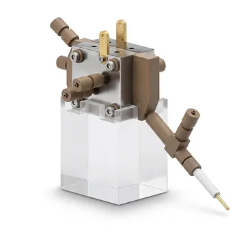
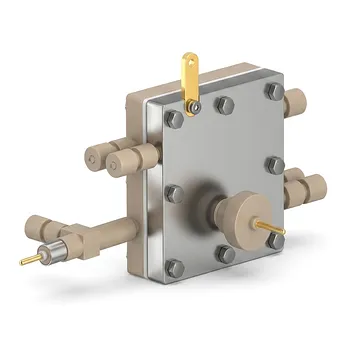
CNC-machined fluoropolymer cells can be designed around the required electrode dimensions, sampling ports, fluid fittings, mixing arrangement, and electrode spacing. This enables consistent exposure area and repeatable hydrodynamic conditions across experiments.
A sealed or well-controlled lid can also reduce external contamination while allowing electrical connections and sampling to be managed without disturbing the cell configuration.
What the Experimental Workflow Looks Like
Prepare and characterize the electrolyte
Researchers prepare the PFOA solution with the selected supporting electrolyte and record the initial concentration, volume, conductivity, and relevant background ion concentrations. Blank solutions without PFOA help identify contamination or electrochemical changes caused by the electrolyte and cell alone.
All wetted components should be cleaned and verified before use, especially when fluoride measurements are central to the study.
Apply a defined current density
The selected anode and counter-electrode are installed at a controlled spacing. A constant current density is then applied, with the electrode area and current recorded so that the operating condition is reproducible.
For comparative studies, the electrolyte composition, initial PFOA concentration, temperature, mixing, electrode area, and electrolysis time should be held constant while the anode material is changed.
Collect time-resolved samples
Samples are withdrawn at predetermined intervals, such as during a 90-minute electrolysis period. Each sample can be divided for PFOA analysis, fluoride measurement, and, where available, intermediate-product characterization.
Time-resolved sampling reveals whether PFOA removal is rapid initially, whether the reaction slows, and whether fluoride release follows or lags behind parent-compound degradation.
Compare the two performance metrics
The final assessment should report at least:
- Residual PFOA concentration.
- PFOA degradation efficiency.
- Observed pseudo-first-order rate constant.
- Fluoride concentration and defluorination percentage.
- Electrolysis time and applied current density.
- Anode composition and electrode area.
- Supporting electrolyte and cell-material controls.
This combination prevents a high apparent degradation rate from being mistaken for complete defluorination.
Understanding the Trade-offs
Higher degradation does not necessarily mean higher defluorination
An anode may remove PFOA from the measured parent-compound pool efficiently while producing persistent fluorinated intermediates. Electrode selection should therefore be based on both PFOA removal and fluoride recovery.
Current density affects energy use and reaction behavior
Increasing current density can change the rate of oxidation, reactive-species generation, gas evolution, and mass transfer. It may improve treatment performance, but it can also increase energy consumption or promote competing reactions.
Current density should be optimized experimentally rather than treated as an isolated indicator of performance.
Electrode composition introduces material-specific concerns
Ti/SnO₂–Sb, Ti/SnO₂–Sb/PbO₂, and Ti/SnO₂–Sb/MnO₂ electrodes can produce different oxidation efficiencies and reaction pathways. Their stability and possible contribution of electrode-derived species should be checked during testing.
An anode that performs well initially may not be suitable for extended operation if its coating degrades or alters the solution chemistry.
Fluoropolymer cells improve control but are not a substitute for controls
PTFE and PFA provide strong chemical resistance and low-interference construction, but they do not eliminate the need for blanks, recovery checks, replicate experiments, and analytical validation.
The most reliable conclusions come from combining inert cell materials with a documented fluorine mass balance and appropriate electrochemical controls.
Making the Right Choice for Your Goal
The cell should be designed around the measurement that defines success, not only around the disappearance of PFOA.
- If your primary focus is PFOA degradation rate: Use a controlled anode, constant current density, fixed electrolyte composition, and time-resolved PFOA measurements to calculate pseudo-first-order kinetics.
- If your primary focus is true defluorination: Measure released fluoride alongside residual PFOA and perform blanks and mass-balance checks to distinguish C–F bond cleavage from conversion to fluorinated intermediates.
- If your primary focus is electrode comparison: Keep electrode area, spacing, mixing, electrolyte, concentration, and electrolysis time constant while comparing Ti/SnO₂–Sb, Ti/SnO₂–Sb/PbO₂, and Ti/SnO₂–Sb/MnO₂ anodes.
- If your primary focus is analytical reliability: Use high-purity PTFE or PFA for wetted cell components, verify low background contamination, and design the cell for repeatable sampling and electrode placement.
- If your primary focus is scale-up: Report current density, energy demand, electrode stability, fluoride recovery, and product distribution rather than relying on PFOA removal alone.
A well-designed electrochemical cell turns PFOA treatment from a simple disappearance test into a controlled assessment of degradation, defluorination, reaction kinetics, and experimental reliability.
Summary Table:
| Metric | Definition | Typical Value |
|---|---|---|
| PFOA Degradation Efficiency | (1 - C_t/C_0) × 100% | >90% within 90 min |
| Pseudo-First-Order Rate Constant | k_obs from ln(C_0/C_t) vs time | Varies |
| Defluorination Efficiency | (F- released / theoretical F from degraded PFOA) × 100% | Up to 77% within 90 min |
| Current Density | Applied current per electrode area | ~10 mA/cm² |
| Anode Materials | Ti/SnO₂–Sb, Ti/SnO₂–Sb/PbO₂, Ti/SnO₂–Sb/MnO₂ | Various |
Elevate your PFOA degradation studies with high-purity PTFE and PFA electrochemical cells from KINTEK. Our custom CNC-machined fluoropolymer components ensure minimal interference, reproducible results, and superior chemical resistance. Whether you need standard labware, custom electrode cells, or complete setups, we supply the precision tools to achieve accurate defluorination metrics. Contact us today to discuss your requirements and enhance your research.
Related Products
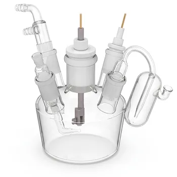
- Conventional Five Port Electrochemical Cell Borosilicate Glass Jacketed Three Electrode System
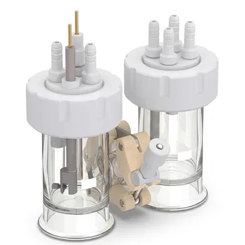
- H Type Replaceable Membrane Electrochemical Cell for Three Electrode System Jacketed Single Layer Gas Purging
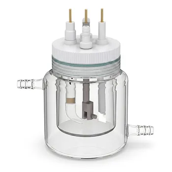
- Sealed Glass Electrochemical Cell with Jacketed Temperature Control and Chemical Resistant PTFE Lid
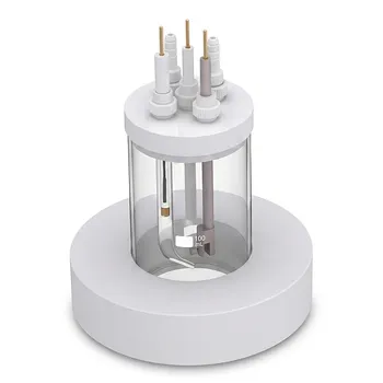
- All Quartz Mini Photoelectrochemical Cell Open System for Spectroscopy and Electrochemistry
- Straight Five Port Hermetic Electrochemical Cell with Internal Plug In Design and PTFE Lid
People Also Ask
- How is cyclic voltammetry performed on fluoropolymer-modified electrodes within electrochemical cells, and what factors affect energy bandgap calculations?
- What factors should be considered when performing cyclic voltammetry and spectroelectrochemistry in custom electrochemical cells to characterize redox-active polymers? Discover key design and analysis tips.
- How does the electroactive β-phase in fluoropolymer battery separators enhance lithium-ion transport, and why are custom electrochemical cells necessary for evaluating these membrane performance characteristics?
- How do sol-gel ceramic-like coatings compare to fluoropolymer materials regarding maximum temperature capability and hardness? Discover the key differences for fluid processing and surface coating applications.