The three-electrode electrochemical system is the essential configuration for evaluating MoS2/CQD electrocatalysts, consisting of a working electrode, a counter electrode, and a reference electrode. This setup allows researchers to precisely isolate and measure the electrochemical behavior of the MoS2/CQD material by decoupling the potential measurement from the current-carrying circuit. By using a dedicated reference point, the system ensures that the data collected—such as overpotential and reaction kinetics—reflects the intrinsic performance of the catalyst rather than systemic interference.
The core value of the three-electrode system lies in its ability to eliminate interference from counter electrode polarization, providing a stable environment for measuring the precise redox characteristics of a catalyst. This configuration is the industry standard for obtaining accurate, reproducible data on catalytic activity and stability.
The Architecture of the Three-Electrode System
The Working Electrode (WE)
The working electrode serves as the platform for the MoS2/CQD electrocatalyst, typically deposited onto a conductive substrate like carbon cloth or glassy carbon. This is the site where the specific chemical reaction of interest, such as the hydrogen evolution reaction (HER), actually takes place.
The Reference Electrode (RE)
The reference electrode, often an Ag/AgCl or saturated calomel electrode, provides a constant and known chemical potential. Because no significant current flows through this electrode, its potential remains stable, acting as a reliable "yardstick" to measure the working electrode's response.
The Counter Electrode (CE)
The counter electrode, usually a graphite rod or platinum wire, completes the electrical circuit by facilitating the opposite reaction to the one occurring at the working electrode. Its primary role is to allow current to flow through the cell without limiting the overall reaction rate.
Why This Configuration is Mandatory for Catalyst Evaluation
Elimination of Counter Electrode Polarization
In a simple two-electrode system, the measured potential is the difference between both electrodes, meaning any instability at the counter electrode skews the results. The three-electrode setup ensures that polarization effects at the counter electrode do not contaminate the measurement of the MoS2/CQD catalyst.
Precise Potential Control
By utilizing a high-precision electrochemical workstation, the system can regulate the potential of the working electrode with millivolt accuracy. This is critical for determining the onset overpotential, which is the exact point at which the MoS2/CQD catalyst begins to drive a chemical reaction.
Accurate Kinetic Analysis
This configuration is necessary to derive the Tafel slope, a key metric that describes the relationship between the overpotential and the reaction rate. Without the stability provided by a reference electrode, calculating the true reaction kinetics of the MoS2/CQD interface would be impossible.
Understanding the Trade-offs and Technical Limits
The Impact of Internal Resistance (iR Drop)
Even with a three-electrode setup, the electrolyte itself has a resistance that can cause a voltage drop, known as iR drop. If this is not mathematically compensated for during testing, the MoS2/CQD catalyst may appear less efficient than it actually is.
Reference Electrode Stability
Reference electrodes are sensitive to temperature and chemical contamination from the electrolyte. If the Ag/AgCl electrode leaks or becomes contaminated, the entire potential scale shifts, leading to incorrect reporting of catalytic activity.
Counter Electrode Interference
While the system minimizes interference, using a platinum counter electrode in certain reactions can lead to "platinum poisoning," where trace amounts of platinum dissolve and redeposit onto the working electrode. This can lead to a false inflation of the MoS2/CQD catalyst's perceived performance.
Applying This System to Your Catalyst Research
How to Maximize Data Integrity
The choice of electrodes and settings should be dictated by the specific medium and the expected current density of your MoS2/CQD material.
- If your primary focus is determining intrinsic activity: Prioritize a three-electrode setup with a Luggin capillary to place the reference electrode as close as possible to the working electrode, minimizing iR drop.
- If your primary focus is long-term stability testing: Use a graphite rod instead of a platinum wire as the counter electrode to prevent any "dissolution-deposition" effects that could mask the degradation of your MoS2/CQD catalyst.
- If your primary focus is understanding electron transfer: Utilize Electrochemical Impedance Spectroscopy (EIS) within the three-electrode configuration to map the charge-transfer resistance at the catalyst surface.
Precise electrochemical evaluation requires the strict isolation of the catalyst's interface through a calibrated three-electrode configuration.
Summary Table:
| Component | Role | Function in MoS2/CQD Testing |
|---|---|---|
| Working Electrode (WE) | Catalyst Host | Site where the HER or redox reaction occurs (e.g., carbon cloth). |
| Reference Electrode (RE) | Potential Standard | Provides a stable potential (Ag/AgCl) for accurate voltage measurement. |
| Counter Electrode (CE) | Circuit Closer | Completes the electrical loop via graphite or platinum wires. |
| Workstation | Control Hub | Regulates potential and measures current with millivolt accuracy. |
Optimize Your Catalyst Research with KINTEK’s High-Performance Solutions
Precise electrochemical evaluation of MoS2/CQD catalysts requires high-purity materials and reliable configurations. At KINTEK, we specialize in manufacturing an exhaustive range of laboratory supplies crafted from PTFE and PFA to ensure maximum chemical resistance and zero contamination.
From high-purity trace analysis instruments and advanced electrochemical cells to essential labware like beakers, centrifuge tubes, and high-volume consumables (O-rings, gaskets, and tubing), we cover every aspect of your experimental setup. Our expertise extends to custom CNC fabrication, allowing us to deliver bespoke non-standard machined parts and advanced reaction apparatus tailored to your specific research needs.
Ready to enhance your lab's data integrity? Contact us today to discover how KINTEK’s fluoropolymer expertise and end-to-end manufacturing can deliver the precision your research deserves!
References
- Fani Rahayu Hidayah Rayanisaputri, Vivi Fauzia. The Role of Solvent in Carbon Quantum Dot Synthesis on the Performance of MoS<sub>2</sub> Nanosheet/Carbon Quantum Dot Heterostructures as Electrocatalysts for the Hydrogen Evolution Reaction. DOI: 10.1021/acsanm.4c06067
This article is also based on technical information from Kintek Knowledge Base .
Related Products
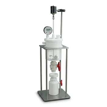
- Customizable PTFE Reaction Vessel with Electric Stirring Paddle and Buchner Funnel Vacuum Filtration System
- Corrosion Resistant PTFE Electrochemical Cell for New Energy Research Inert Insulating Customizable Lab Reaction Vessel
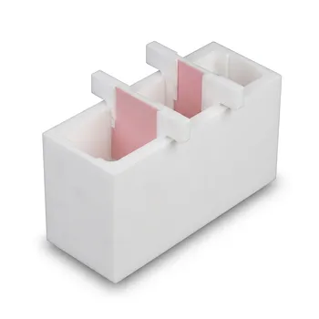
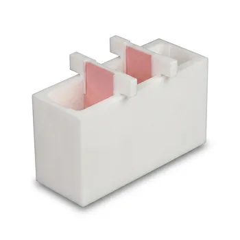
- Square PTFE Electrochemical Cell for Silicon Wafer Processing and Hydrofluoric Acid Resistance in Semiconductor and New Energy Research
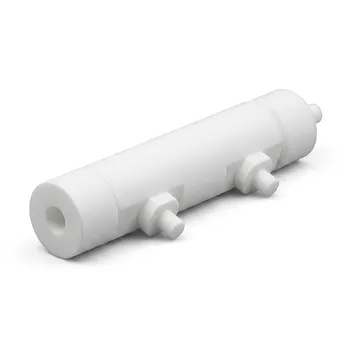
- Custom PTFE Electrolytic Cell Corrosion Resistant Low Background Reaction Vessel with Inlet Outlet Ports
- Customizable Graphite Aluminum Alloy Electric Acid Evaporation System for Laboratory Digestion Pretreatment with Multi Hole Configurations
People Also Ask
- Why are fluoroplastic (PTFE) reaction vessels recommended for Methylene Blue (MB) adsorption kinetic experiments?
- Why are high-purity PTFE or PFA reaction vessels recommended for the synthesis of PANI-TiC hybrid materials? - Guide
- What reaction vessel and fluid handling considerations are necessary for living cationic polymerization of fluorinated monomers involving Lewis acid catalysts? Key design and safety tips
- Why is a PTFE reaction vessel required for Ti3C2Tx MXene synthesis? Ensure Safe HF Etching & High Purity
- Ion Activation Reaction Vessel Requirements: Why PTFE is Critical for Membrane Performance