Co-feeding C4F8 can increase the net TFE yield by preventing further dimer formation. During chlorodifluoromethane (CF2HCl, also written CHClF2) pyrolysis, C4F8 is an undesirable dimer that consumes fluorocarbon feedstock. Adding approximately 9.0 to 9.9 wt% C4F8 to the feed shifts the reaction equilibrium so that net additional C4F8 production approaches zero, improving the overall production of TFE and HFP. This strategy also requires an analytical system designed for accurate fluorocarbon dosing, chemically resistant flow paths, and contamination-free gas chromatography sampling.
The co-feed does not eliminate C4F8 from the process; it suppresses its net formation. Once the feed contains roughly 9.0-9.9 wt% C4F8, the reactor can reach a condition in which newly formed dimer is effectively offset by the equilibrium established with the recycled dimer, preserving more feedstock for TFE and HFP production.
Why C4F8 Co-Feeding Improves TFE Yield
C4F8 is a competing product
CF2HCl pyrolysis is intended to produce TFE, but it can also generate fluorocarbon byproducts, including C4F8. Formation of this dimer diverts reactive material away from the desired monomer and reduces the effective yield of the process.
The dimer is therefore both a product-quality concern and a feedstock-efficiency concern.
The co-feed shifts the reaction equilibrium
Introducing controlled C4F8 into the reactor feed changes the composition seen by the pyrolysis chemistry. At the appropriate concentration, this composition suppresses the driving force for producing additional C4F8.
The practical result is zero or near-zero net dimer production. The co-fed C4F8 remains part of the process stream rather than being converted into additional unwanted dimer.
The optimum is a narrow operating range
The reported target is approximately 9.0 to 9.9 wt% C4F8 in the feed. Within this range, net dimer production drops to zero and the overall yield of TFE and HFP is maximized.
The concentration must be controlled on a clearly defined basis. A value stated in weight percent should not be treated as mol percent without conversion and confirmation against the process specification.
What This Means for TFE Production
Yield improvement comes from avoiding feedstock loss
The principal benefit is not necessarily that C4F8 directly converts into TFE. The benefit is that less additional feedstock is trapped in newly generated C4F8.
That improves the net material balance for the desired products, especially TFE and HFP.
HFP also responds to the equilibrium shift
The same operating condition that suppresses additional C4F8 formation supports a higher combined yield of TFE and HFP. TFE remains the primary target when monomer production is the priority, while HFP must be monitored because its formation can increase under more severe pyrolysis conditions.
Temperature remains a separate control variable
C4F8 co-feeding addresses the dimerization equilibrium, but it does not replace temperature and residence-time optimization. TFE production is favored at high pyrolysis temperatures, while temperatures above approximately 850 °C can also increase competing HFP formation.
A useful process design therefore treats C4F8 concentration, temperature, residence time, and dilution as related but separate control variables.
How Co-Feeding Changes Laboratory Analytical Design
The feed system must meter C4F8 accurately
The 9.0-9.9 wt% target is narrow enough that imprecise dosing can move the reactor away from the condition that suppresses net dimer formation. The laboratory setup should therefore use calibrated mass-flow control or an equivalent gravimetric or volumetric dosing method suitable for the gas composition and operating pressure.
Feed measurements should be recorded on the same composition basis used to define the target range.
The transfer path must resist fluorocarbon service
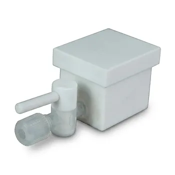
Fluorocarbon streams and high-temperature pyrolysis products can create compatibility and corrosion challenges, particularly where reactive contaminants or moisture are present. PTFE or PFA transfer lines are appropriate choices for corrosion-resistant sample and feed handling when their pressure, temperature, and permeation limits are acceptable for the application.
The transfer path should be short, well-characterized, and arranged to minimize dead volume where possible.
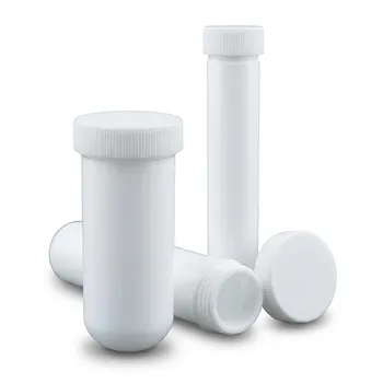
The system needs reliable high-purity vessels
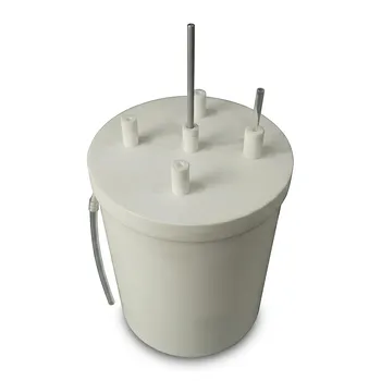
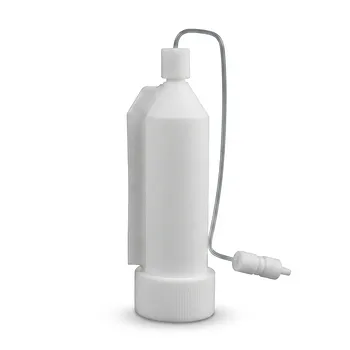
C4F8 and CF2HCl must reach the reactor and analytical instrument without dilution, adsorption, leakage, or cross-contamination. High-purity cylinders, regulators, valves, and transfer vessels help preserve the intended feed composition.
Every wetted component should be evaluated for chemical compatibility, pressure rating, cleanliness, and potential outgassing.
Gas chromatography becomes a process-control instrument
Gas chromatography should quantify at least TFE, C4F8, HFP, and unreacted feed components where the method permits. The critical calculation is not simply the measured C4F8 concentration in the outlet, but the difference between the amount fed and the amount formed after accounting for the co-fed dimer.
This distinction is necessary to determine whether the process has reached zero net dimer production.
Sampling must preserve the original gas composition
Reactive fluorocarbon samples can be distorted by condensation, adsorption, leaks, or incompatible materials before they reach the chromatograph. Heated or temperature-controlled sections may be required where condensation is possible, while excessive sample-line temperature should be avoided if it can promote secondary reactions.
The sampling valve, loop, lines, and vessel materials should be validated together rather than selected independently.
The Role of Dilution and Reactor Conditions
Steam can improve conversion at lower temperatures
Supplementary process information indicates that steam dilution can substantially improve CF2HCl conversion. At a steam-to-CF2HCl ratio of approximately 8.0, conversion can exceed 90% around 750-800 °C, where conversion without dilution is much lower.
This can be useful when reducing the temperature burden is important.
High temperature can increase HFP formation
Although TFE yield is generally favored at temperatures above approximately 900 °C, more severe conditions can increase competing reactions and HFP production. The best condition is therefore not defined by temperature alone.
Analytical monitoring is needed to distinguish higher conversion from genuinely improved TFE selectivity.
Residence time must be measured and controlled
Typical residence times in the referenced systems range from approximately 0.19 to 2.0 seconds. Small changes can affect conversion, secondary reactions, and the balance between TFE, HFP, and C4F8.
The reactor design should provide a known heated volume and a controlled flow rate so that residence time can be calculated and reproduced.
Understanding the Trade-offs
Co-feeding consumes capacity in the material balance
The co-fed C4F8 is not an inert additive in the broad process sense. It occupies part of the feed composition and must be recovered, recycled, or otherwise managed downstream.
The economic benefit depends on whether suppressing new dimer formation outweighs the handling and recycling requirements for the co-fed dimer.
An incorrect concentration basis can invalidate the optimization
Confusing weight percent with mol percent can produce a materially different feed composition. This is a common analytical and process-design error when comparing literature values, gas-cylinder specifications, and chromatographic results.
The laboratory procedure should explicitly state whether each composition is reported by mass, mole, volume, or another basis.
More conversion does not always mean more TFE
Steam dilution may improve CF2HCl conversion, and higher temperature may increase overall reaction severity, but either change can also alter byproduct formation. A setup that measures only conversion cannot establish that TFE yield has improved.
The analytical method should report both conversion and product selectivity.
Fluorocarbon compatibility is not sufficient by itself
PTFE and PFA provide useful corrosion resistance, but material selection must still consider pressure, temperature, permeation, mechanical strength, valve construction, seals, and cleaning procedures. Components outside the fluoropolymer-lined path can remain vulnerable to corrosion or contamination.
A complete compatibility review is required for the entire sampling and feed system.
Making the Right Choice for Your Goal
The operating and analytical priorities should follow the result the laboratory needs to demonstrate.
- If your primary focus is maximizing net TFE yield: Establish and maintain approximately 9.0-9.9 wt% C4F8 in the feed, then verify the result through a material balance that distinguishes co-fed dimer from newly formed dimer.
- If your primary focus is maximizing total TFE and HFP production: Optimize C4F8 co-feed together with temperature, residence time, and dilution rather than treating dimer suppression as an isolated control.
- If your primary focus is reliable laboratory measurements: Use calibrated gas dosing, high-purity transfer vessels, compatible PTFE/PFA flow paths, and a GC method that quantifies both feed and outlet compositions.
- If your primary focus is process development: Report composition basis, temperature, residence time, dilution ratio, conversion, selectivity, and net C4F8 formation together so that each experiment can be reproduced and compared.
A properly controlled C4F8 co-feed turns an unwanted dimer pathway into a manageable equilibrium variable while giving the analytical system the precision needed to confirm the TFE yield benefit.
Summary Table:
| Aspect | Impact/Requirement |
|---|---|
| C4F8 Co-feed Concentration | Optimal range: 9.0–9.9 wt% to suppress net dimer formation, maximizing TFE/HFP yield. |
| TFE Yield | Increased by preventing feedstock loss to C4F8; near-zero net C4F8 production. |
| HFP Yield | May increase under severe conditions; monitor separately. |
| Feed System | Requires precise mass-flow control for C4F8 dosing. |
| Transfer Lines | Use PTFE/PFA for corrosion resistance, short paths to minimize dead volume. |
| Vessels & Components | High-purity, compatible materials to avoid contamination. |
| GC Analysis | Must quantify TFE, C4F8, HFP, and unreacted feed; calculate net C4F8 formation. |
| Sampling | Heated/temperature-controlled to preserve composition; validate all materials. |
| Dilution (Steam) | Can improve conversion (e.g., >90% at ~750-800°C with 8:1 steam). |
| Residence Time | Control 0.19–2.0 s for reproducibility and selectivity. |
Optimize your TFE production with precision fluoropolymer lab equipment. KINTEK offers high-performance PTFE and PFA labware, custom machining, and gas handling components designed for demanding pyrolysis studies. Ensure accurate C4F8 co-feeding and reliable analytics with our corrosion-resistant solutions. Contact us today to discuss your custom requirements and elevate your laboratory's performance. Our experts are ready to support your process development with end-to-end PTFE/PFA solutions—from standard labware to bespoke reaction apparatus.
Related Products
- High Purity PTFE Reaction Vessel with Electric Stirring System and Customizable 5L Tank including Buchner Funnel Filtration Assembly
- Custom PTFE Reaction System with Hose Barb Fittings Corrosion Resistant High Sealing 2L 4L Lab Reactor with Separatory Funnel
- Custom PTFE Condensation Reflux Apparatus with Serpentine Coil and Flask Collection System for Corrosive Chemical Processing
- Customizable PTFE Reaction Vessel with Electric Stirring Paddle and Buchner Funnel Vacuum Filtration System
- High Purity Custom PTFE Laboratory Reaction Tank with Baffles for Low Background Trace Analysis
People Also Ask
- Why are fluoroplastic (PTFE) reaction vessels recommended for Methylene Blue (MB) adsorption kinetic experiments?
- Ion Activation Reaction Vessel Requirements: Why PTFE is Critical for Membrane Performance
- Why is a PTFE reaction vessel required for Ti3C2Tx MXene synthesis? Ensure Safe HF Etching & High Purity
- Why are high-purity PTFE or PFA reaction vessels recommended for the synthesis of PANI-TiC hybrid materials? - Guide
- How do perfluorinated solvent environments influence the selection of reaction vessels and fluid handling components in nonaqueous emulsion polymerizations? Choose fluoropolymer materials.