Re-entrant surface geometry enables fluoropolymer vessels to repel low-surface-tension liquids by preventing droplets from fully wetting the texture. On a flat fluoropolymer surface, oils and organic solvents often have equilibrium contact angles below 90°, so they spread and penetrate ordinary roughness in the Wenzel state. A re-entrant texture creates an overhang with a local texture angle below 90°, allowing the liquid’s contact line to become pinned while air remains trapped beneath the droplet in a Cassie–Baxter state.
The fluoropolymer provides chemical resistance and low surface energy; the re-entrant geometry provides the capillary barrier that preserves air pockets and prevents low-surface-tension solvents from spreading into the surface texture.
Why Conventional Surface Roughness Is Not Enough
Low surface tension drives spreading
Oils, alcohols, and many organic solvents have substantially lower surface tension than water. On a flat fluoropolymer, their equilibrium contact angles may be less than 90°, which favors spreading rather than droplet formation.
When a conventional texture is added, the liquid can enter the surface grooves. This produces a fully wetted Wenzel state, where roughness often increases the effective area of liquid–solid contact instead of improving repellency.
Fluoropolymer chemistry has limits
Fluoropolymers are intrinsically low-energy and chemically resistant, making them suitable for aggressive solvents and reaction environments. However, low surface energy alone does not guarantee oil repellency, particularly when the liquid’s equilibrium contact angle is below 90°.
The chemical composition and the surface geometry solve different problems: the fluoropolymer supports compatibility, while the texture controls whether the liquid can invade the surface.
How Re-Entrant Geometry Prevents Wetting
The overhang supports the contact line
A re-entrant texture includes an overhanging or inward-curving feature rather than a simple peak-and-valley roughness pattern. Its local texture angle, represented as ψ, is less than 90°.
As the liquid advances, the three-phase contact line—where solid, liquid, and air meet—can encounter the overhang. The geometry can reach a condition where the local texture angle matches the liquid’s equilibrium contact angle, expressed as ψ = θ.
Air remains trapped beneath the droplet
At this geometric condition, advancing the liquid farther would require the contact line to overcome an unfavorable capillary configuration. The liquid therefore remains suspended across portions of the texture, with air trapped underneath.
This creates a composite Cassie–Baxter interface, consisting of liquid contacting solid features and air occupying the spaces between them.
The result is apparent superoleophobicity
Because the droplet rests partly on air rather than fully contacting the solid, the measured or apparent contact angle can become much larger than the equilibrium contact angle on a flat surface. Well-designed structures can produce apparent contact angles above 150° and low contact angle hysteresis.
Low hysteresis is important because it allows droplets to roll or slide away rather than remain pinned as stationary, contaminated residues.
Design Requirements for Reaction Vessels and Containers
Geometry must be re-entrant, not merely rough
A texture that only increases roughness may improve water repellency but still fail against oils and organic solvents. For low-surface-tension liquids, the critical feature is the re-entrant curvature or overhang that stabilizes the composite interface.
This principle can be applied to vessel walls, container interiors, fluidic components, and other fluoropolymer surfaces where residue-free drainage is important.
The spacing ratio controls trapped air
The spacing ratio, D*, describes the relationship between the surface features and their spacing, and therefore relates to surface porosity and the fraction of air that can remain trapped.
A design with D* much greater than 1 is associated with a greater ability to maintain the intended composite interface. The exact geometry still must be matched to the liquid, feature dimensions, and operating conditions.
The robustness factor controls breakthrough resistance
The robustness factor, A*, represents the ratio between the liquid breakthrough pressure and a capillary reference pressure. It indicates how effectively the texture resists forced liquid penetration.
Designing for A* much greater than 1 helps prevent pressure, impact, or handling from driving the solvent into the texture and causing a transition to the Wenzel state.
What This Means in Chemical Use
Reduced wetting and staining
When the Cassie–Baxter state remains stable, solvents and oils have less opportunity to spread across or penetrate the vessel wall. Droplets can detach more readily, reducing residual films and visible staining.
This is especially useful where carryover, cleaning effort, or contamination between reaction steps matters.
Chemical compatibility remains essential
Re-entrant geometry does not make an incompatible polymer chemically compatible. The fluoropolymer must still be selected for the solvent, temperature, concentration, exposure time, and reaction conditions.
The texture improves interfacial behavior; it does not replace chemical-resistance testing or process validation.
Understanding the Trade-offs
Repellency depends on maintaining the air layer
The Cassie–Baxter state is metastable rather than guaranteed under every condition. Sufficient pressure, impact, prolonged exposure, or defects can force liquid through the texture.
Once breakthrough occurs, the liquid may transition to a Wenzel state and become more strongly retained.
Texture durability can limit real-world performance
A delicate re-entrant structure may lose effectiveness if it is damaged, abraded, compressed, or fouled by particles and reaction residues. A design intended for reusable labware must balance high repellency with mechanical robustness and cleanability.
Contact angle alone is not enough
A high static contact angle does not fully describe container performance. Contact angle hysteresis, droplet mobility, breakthrough pressure, and resistance to repeated use are also important.
A surface that initially shows a very high angle may still retain solvent if the contact line is strongly pinned or if pressure collapses the trapped-air interface.
Manufacturing imposes practical constraints
Re-entrant features must be produced consistently across the relevant vessel area, including corners, seams, openings, and curved walls. Nonuniform feature dimensions can create localized wetting sites where solvents begin to penetrate.
How to Apply This to Your Project
The most reliable design approach combines fluoropolymer chemistry with geometry and pressure-resistance testing.
- If your primary focus is maximum solvent repellency: Use a fluoropolymer surface with genuinely re-entrant features, targeting a stable Cassie–Baxter interface rather than relying on ordinary roughness.
- If your primary focus is resistance to pressure-driven wetting: Optimize the texture for a high robustness factor A* so the liquid breakthrough pressure exceeds the expected operating stresses.
- If your primary focus is low residue and easy drainage: Prioritize low contact angle hysteresis and sufficient spacing design, represented by D*, so droplets can detach without remaining pinned.
- If your primary focus is reusable reaction vessels: Validate the texture after chemical exposure, cleaning, abrasion, and repeated use, not only in its initial laboratory condition.
- If your primary focus is chemical process reliability: Verify both the fluoropolymer’s chemical compatibility and the textured surface’s ability to retain its composite interface under actual solvent, temperature, and pressure conditions.
The key is to treat fluoropolymer chemistry as the compatibility foundation and re-entrant geometry as the capillary mechanism that makes low-surface-tension solvent repellency possible.
Summary Table:
| Parameter | Role in Repellency | Design Target |
|---|---|---|
| Surface Energy (Chemistry) | Provides low adhesion and chemical compatibility | Use fluoropolymer (PTFE/PFA) |
| Re-entrant Texture (ψ < 90°) | Creates capillary barrier to trap air | Optimize overhang profile |
| Spacing Ratio (D*) | Determines trapped air fraction; high D* favors Cassie-Baxter | D* >> 1 |
| Robustness Factor (A*) | Measures resistance to breakthrough under pressure | A* > 1 for process stability |
| Contact Angle Hysteresis | Low hysteresis promotes droplet roll-off and low residue | Minimize pinning |
Need high-performance fluoropolymer vessels that resist solvent wetting? Contact KINTEK today for custom PTFE/PFA reaction vessels and containers engineered with re-entrant surface geometry to minimize contamination and maximize chemical compatibility. Our advanced CNC machining and tailored surface texturing help you achieve superior solvent repellency and easy cleaning, boosting productivity in your lab or process.
Related Products
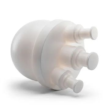
- High Purity Custom PTFE Large Volume 15L Flask Corrosion Resistant Low Trace Background Fluoropolymer Reaction Vessel
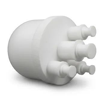
- Laboratory PTFE Three Neck Reaction Flask Corrosion Resistant 2000ml Low Background Fluoropolymer Vessel
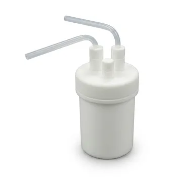
- Custom PTFE Continuous Reaction Bottles Virgin Fluoropolymer High Purity Low Background Synthesis Vessels
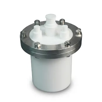
- Custom PTFE Reaction Kettle 2L Flanged Fluoropolymer Reactor Tank Acid and Alkali Resistant Polytetrafluoroethylene Vessel
- Large Capacity PTFE Reaction Bottle 2L Wide Mouth Fluoropolymer Extraction Vessel Compatible with Rotary Agitators
People Also Ask
- What toxicological hazards and safe handling protocols must be established when PTFE fluoropolymer reaction vessels are subjected to pyrolysis temperatures? Learn essential safety measures now.
- Why are high-purity PTFE or PFA reaction vessels recommended for the synthesis of PANI-TiC hybrid materials? - Guide
- How do perfluorinated solvent environments influence the selection of reaction vessels and fluid handling components in nonaqueous emulsion polymerizations? Choose fluoropolymer materials.
- What reaction vessel and fluid handling considerations are necessary for living cationic polymerization of fluorinated monomers involving Lewis acid catalysts? Key design and safety tips
- Ion Activation Reaction Vessel Requirements: Why PTFE is Critical for Membrane Performance