Solid PTFE is difficult to stretch by conventional thermoplastic methods because it does not become a freely flowing melt. Its extremely high molecular weight, high crystallinity, rigid carbon-fluorine backbone, and high melting temperature produce exceptionally high melt viscosity. At conventional slow strain rates, typically below 5 cm/min, PTFE tends to fracture before it can elongate significantly; porous expanded PTFE, or ePTFE, is therefore made by rapidly stretching prepared PTFE at elevated temperature to create interconnected nodes and microscopic fibrils.
The key distinction is that PTFE must be shaped primarily as a solid or paste, then rapidly expanded under carefully controlled thermal and mechanical conditions. The expansion process separates solid nodes while drawing fibrils between them, producing a strong, chemically resistant porous membrane.
Why Conventional Thermoplastic Processing Fails
PTFE Does Not Flow Like Standard Thermoplastics
Most thermoplastics can be heated above their melting point until they become sufficiently fluid for extrusion or injection molding. PTFE is an exception: even above its crystalline melting range of approximately 327-340 °C, its melt viscosity remains extremely high.
This behavior results largely from PTFE's exceptionally high molecular weight, commonly reported in the range of 1 × 10⁶ to 5 × 10⁶ g/mol, together with its rigid fluorinated molecular structure.
The Processing Window Is Narrow
PTFE must be heated above its crystalline melting point to become more deformable, but temperatures above roughly 410 °C can cause rapid thermal degradation. The range between melting and degradation therefore does not provide the broad, low-viscosity processing window available for conventional thermoplastics.
PTFE can also fracture under shear in this temperature range rather than flow smoothly through conventional molding equipment.
Slow Stretching Causes Premature Fracture
At conventional slow strain rates, PTFE cannot sufficiently rearrange its highly crystalline, tightly packed structure. Applied stress therefore concentrates in the solid material, causing cracks or fracture before substantial elongation occurs.
This is why simply pulling a solid PTFE sample slowly usually produces little useful expansion and a broken specimen rather than a porous membrane.
How PTFE Is Prepared for Expansion
Shaping the Solid or Paste Precursor
Because ordinary melt extrusion and injection molding are unsuitable, PTFE is commonly processed using methods such as cold compression molding followed by sintering, paste extrusion, or machining.
For ePTFE production, a PTFE powder is typically formed into a suitable precursor, often through paste-based processing. The precursor is then consolidated or sintered sufficiently to provide a continuous material that can be expanded.
Processing Resembles Powder Consolidation
PTFE processing has more in common with powder metallurgy than with standard melt processing. Fine PTFE particles are compacted, shaped, and thermally treated rather than simply melted and pumped through a die.
The resulting precursor must have enough integrity to withstand rapid drawing while retaining the structural characteristics needed to form pores.
How the Porous Membrane Is Produced
Rapid Expansion at Elevated Temperature
The consolidated PTFE precursor is heated to an elevated temperature and stretched rapidly. The temperature improves molecular mobility and reduces the likelihood of immediate fracture, while the high expansion rate enables PTFE to deform in a distinctive way.
The process may use one or more drawing directions, depending on the required membrane properties and product geometry.
Nodes and Fibrils Form the Pore Network
During rapid expansion, portions of the PTFE remain as relatively dense solid regions called nodes. Fine strands called fibrils are drawn between these nodes.
The spaces between the nodes and fibrils become the membrane's interconnected pores. This produces a structure that is porous enough for gas or liquid transport while retaining a continuous fluoropolymer network for mechanical strength.
Stretching Controls the Final Structure
The stretching rate, temperature, and draw ratio strongly influence the membrane's morphology. These variables affect node spacing, fibril length, pore size, porosity, and air permeability.
Higher stretch ratios and appropriately optimized temperatures generally increase the spacing between nodes and extend the fibrils. The process must remain controlled, however, because excessive or poorly timed stretching can damage the network.
Why ePTFE Is Useful
Chemical Resistance
The fluorinated PTFE structure provides strong resistance to aggressive chemicals, solvents, and concentrated acids. This makes ePTFE suitable for demanding filtration, venting, and sealing applications.
Porosity With Mechanical Integrity
The node-fibril network combines open transport paths with a strong polymer framework. That combination allows ePTFE membranes to support filtration or venting without behaving like an unconsolidated powder.
Application Flexibility
Depending on its pore structure and thickness, ePTFE can be used for chemical filtration, sample preparation, fluid separation, protective venting, and high-performance sealing.
Understanding the Trade-offs
More Porosity Can Reduce Barrier Performance
Increasing the draw ratio can enlarge pores and improve permeability, but it can also reduce resistance to particle passage, liquid breakthrough, or pressure-driven flow. The correct structure depends on whether the product prioritizes filtration, venting, separation, or sealing.
Processing Requires Tight Thermal Control
The material must be hot enough to expand without fracturing, but it must remain below conditions that cause rapid thermal degradation. Small changes in temperature can therefore affect both process stability and membrane performance.
Stretching Is Not the Only Membrane Method
Porous fluoropolymer membranes can also be produced by phase inversion, electrospinning, thermal sintering, or track etching. These methods generate different pore geometries and surface structures, so they are not interchangeable with the rapid-expansion route used to produce ePTFE.
Different Membrane Structures Serve Different Jobs
Rapidly expanded PTFE produces a characteristic node-fibril network. Track etching, for example, can create more uniform cylindrical pores, while electrospinning produces a nanofibrous nonwoven structure.
The appropriate method should therefore be selected based on pore-size distribution, permeability, mechanical strength, chemical compatibility, and the intended filtration or separation task.
How to Apply This to Your Project
The processing choice should follow the required balance between expansion, pore structure, strength, and chemical performance.
- If your primary focus is conventional PTFE shaping: Use powder-based consolidation, paste extrusion, sintering, or machining rather than relying on ordinary injection molding or melt extrusion.
- If your primary focus is an ePTFE membrane: Form and consolidate a PTFE precursor, then rapidly expand it at an elevated temperature under controlled draw conditions.
- If your primary focus is pore-size control: Adjust the expansion temperature, stretching rate, and draw ratio while measuring the resulting pore structure and permeability.
- If your primary focus is a different porous architecture: Evaluate phase inversion, electrospinning, thermal sintering, or track etching instead of assuming that rapid PTFE expansion is the best route.
Understanding PTFE as a high-viscosity, solid-state-processable fluoropolymer explains both why conventional stretching fails and why rapid controlled expansion produces a strong porous membrane.
Summary Table:
| Aspect | Conventional Thermoplastic Processing | PTFE Expansion (ePTFE) |
|---|---|---|
| Melt behavior | Flows readily above melting point | Extremely high melt viscosity; does not flow freely |
| Strain rate | Slow rates typical | Rapid stretching required ( >5 cm/min) |
| Temperature range | Broad processing window | Narrow; between melting (~327°C) and degradation (>410°C) |
| Result of slow stretching | Deforms plastically | Fractures before significant elongation |
| Mechanism | Molecular chain slippage | Nodes and fibrils formation |
| Final structure | Dense, non-porous | Porous network with interconnected pores |
Optimize your PTFE processing with KINTEK's high-performance fluoropolymer solutions. Our PTFE and PFA labware, custom-machined components, and ePTFE membranes are designed for superior chemical resistance and reliability. Whether you need standard labware, filtration systems, or custom parts, our expertise in advanced fluoropolymers ensures your applications perform at their best. Contact us today to discuss your requirements and discover how we can enhance your lab's efficiency. Get in touch with our specialists for personalized support and OEM/ODM partnerships.
Related Products
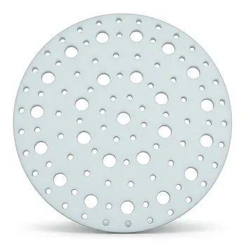
- High Temperature Resistant Insulating TFM Separator and Ultra Clean Laboratory PTFE Baffle Plate with Customizable Pore Size and Hole Configuration
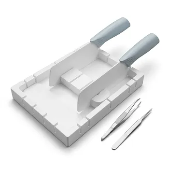
- High Purity PTFE Square Membrane Cutter and Filter Aliquot Device for Trace Analysis and Cleanroom Laboratory Applications
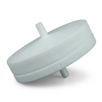
- PTFE Membrane Filter Holder for Aerosol Environmental Monitoring and Low Concentration Particulate Matter Sampling Chemical Resistant Air Quality Analysis Component
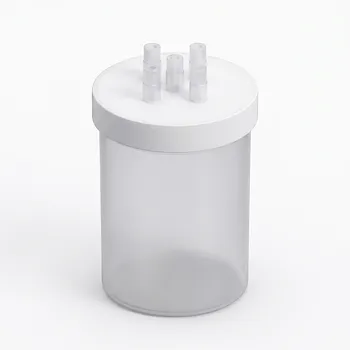
- High Purity 4L PFA Reaction Tank for Proton Exchange Membrane Electrolysis Water Oxygen Separation Systems
- High Purity PTFE Square Membrane Cutter Equipartition Device for Trace Analysis and Disease Control Centers Clean Non Stick No Leaching
People Also Ask
- What are the limitations of pure PTFE in high temperature applications? Understanding the 200°C Ceiling
- Are Teflon parts capable of withstanding high temperatures? Understanding the 260°C Limit for Performance
- What future advancements are expected in temperature-resistant PTFE seals? Discover Smarter, Tougher Sealing Solutions
- What is porous PTFE used for? Advanced Filtration for Harsh Chemical & High-Temp Environments
- What are the benefits of porous PTFE? Unlock Superior Filtration and Chemical Resistance