Oxygen contamination makes CTFE more than a flammable-process concern: it can create unstable peroxide species that initiate runaway polymerization. Even trace oxygen can react with liquid CTFE at low temperatures, producing oxygenated by-products and organic peroxides such as chlorodifluoroacetyl-related species. These compounds may decompose unpredictably, release heat rapidly, and trigger violent, uncontrolled polymerization or pressure generation.
The essential control is oxygen exclusion. A safe CTFE laboratory setup must prevent air ingress during storage, transfer, and reaction by combining degassed fluids, inert-gas blanketing, vacuum-tight equipment, and chemically inert fluoropolymer components. Equipment integrity matters as much as the purge itself: a leak-tight system prevents both peroxide formation and hazardous vapor release.
Why Oxygen Contamination Is Dangerous
Trace oxygen can form unstable reaction products
CTFE can react with oxygen even at relatively low temperatures. The resulting peroxides and oxygenated products are substantially less predictable than the starting monomer.
These materials can accumulate unnoticed in liquid monomer, dead legs, valve cavities, transfer lines, or vessel surfaces if oxygen is repeatedly introduced.
Peroxides can initiate uncontrolled polymerization
Organic peroxides can behave as powerful and unpredictable polymerization initiators. If they decompose or activate within CTFE, polymerization may accelerate faster than heat can be removed.
The resulting exotherm can cause rapid temperature and pressure increases, potentially leading to vessel rupture, violent discharge, or an uncontrolled reaction.
Air ingress creates a continuing hazard
Oxygen contamination is not limited to the initial reactor charge. It can enter through leaking fittings, elastomer seals, poorly purged lines, reagent bottles, sampling ports, or fluid transfers performed under an inadequate inert-gas blanket.
Each air-ingress event can create new opportunities for peroxide formation and accumulation.
Where the Risk Appears in a CTFE Process
Storage containers
CTFE should be stored in systems that prevent contact with air throughout filling, withdrawal, and headspace changes. A container that is sealed only after exposure to air does not solve the contamination problem.
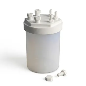
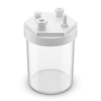
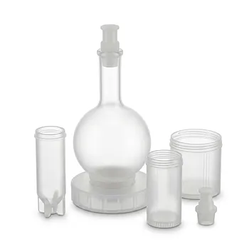
Hermetically sealed PFA reagent bottles and compatible PTFE valve assemblies can help isolate the monomer from oxygen while maintaining chemical resistance.
Transfer manifolds and delivery lines
Transfer equipment is a common contamination point because it combines valves, connections, flexible sections, and changes in pressure. Small leaks may admit air without producing an obvious visible leak of CTFE.
A dedicated, sealed transfer manifold with vacuum capability and fluoropolymer fittings reduces the number of exposure points and makes controlled purging practical.
Reaction vessels
The reactor must maintain an oxygen-free environment during charging, reaction, sampling, and discharge. A system that is inert at the start can still become contaminated through a poorly sealed addition port or a backflow event.
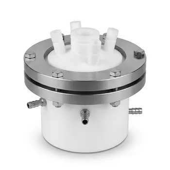
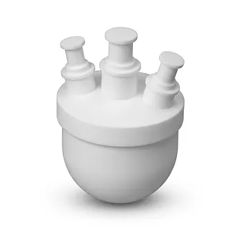
Custom-machined PTFE and PFA vessels provide chemically inert, nonreactive contact surfaces. They must nevertheless be incorporated into a properly engineered pressure- and vacuum-rated assembly; fluoropolymer compatibility alone does not guarantee mechanical safety.
How Specialized Fluoropolymer Setups Reduce the Risk
Use inert-gas blanketing and vacuum purging
Oxygen and air should be removed from vessels, lines, and transfer components before CTFE is introduced. Degassed process fluids and an inert-gas blanket help prevent oxygen from returning through the liquid phase or vessel headspace.
Purging is effective only when the system has an appropriate flow path. Trapped cavities, dead legs, and closed valve sections can retain contaminated gas unless the manifold is designed to evacuate them.
Build for gas-tight integrity
The objective is not simply to use fluoropolymer materials; it is to create a system that remains leak-tight under the actual temperature, pressure, and vacuum conditions.
Important design features include:
- Vacuum-tight fluoropolymer fittings
- Minimized joints and dead-volume regions
- Sealed valves and transfer connections
- Dedicated CTFE delivery paths
- Closed sampling and charging arrangements
- Pressure- and vacuum-rated vessels and components
PTFE and PFA offer strong chemical inertness and low reactivity toward fluorinated monomers. Their performance still depends on correct machining, sealing, support, and inspection.
Use nonreactive internal surfaces
Fluoropolymer surfaces reduce the likelihood that equipment materials will chemically interact with CTFE or oxygenated intermediates. This is especially valuable in small-scale laboratory systems, where deposits in narrow passages can be difficult to inspect.
Smooth, cleanable surfaces also help reduce locations where contaminated liquid or peroxide-bearing residues could remain after a transfer.
Control monomer quality before reaction
Where the process requires it, CTFE may need purification or stabilization using a method validated for the specific polymerization chemistry. Purification systems, such as silica-based columns, and radical inhibitors can affect downstream polymerization behavior and must not be selected casually.
The key principle is to control both oxygen content and monomer condition before the material enters the reactor. Any treatment must be compatible with the intended reaction, storage period, and waste procedure.
Verify oxygen exclusion rather than assuming it
A purge sequence should be supported by a defined verification method, such as oxygen monitoring appropriate to the system and operating range. Leak testing, vacuum-hold checks, and inspection of seals and valves are equally important.
“Purged” is not a measurement. The safety case is stronger when the laboratory can demonstrate that oxygen concentration, pressure behavior, and system integrity meet predetermined limits.
Designing the Laboratory Around Containment
Separate storage, transfer, and reaction functions
A dedicated transfer system reduces repeated disconnections and limits the number of times CTFE containers are exposed to the laboratory environment. It also makes it easier to maintain an inert atmosphere from storage through reaction.
The fewer open handling steps there are, the fewer opportunities exist for oxygen ingress or accidental release.
Provide controlled pressure management
Peroxide formation and polymerization can generate heat and pressure unexpectedly. The system therefore needs pressure-rated components, appropriate relief planning, temperature monitoring, and a means of isolating or stopping the feed when abnormal conditions appear.
Relief and containment decisions must account for the actual CTFE inventory, solvent or fluid composition, temperature, and possible polymerization rate. They should be reviewed by qualified process-safety personnel rather than inferred from material compatibility alone.
Use remote or shielded operation where appropriate
Physical separation, shielding, and remote operation can reduce personnel exposure if a small vessel or line fails. These measures do not replace oxygen control, but they limit consequences when prevention is imperfect.
Laboratory procedures should also define safe shutdown, quarantine, and waste handling for material suspected of containing peroxides.
Understanding the Trade-offs
Fluoropolymer components are not a complete safety system
PTFE and PFA provide valuable chemical inertness and can support excellent sealing performance, but they do not eliminate pressure, temperature, or decomposition hazards.
Some fluoropolymer components may have limited mechanical strength, creep under load, or reduced suitability at particular pressures and temperatures. Component selection must therefore consider mechanical ratings as well as chemical compatibility.
More sealing can complicate inspection and maintenance
A highly closed system reduces oxygen ingress but can make internal inspection, cleaning, and detection of deposits more difficult. Designs should include accessible, controlled inspection points without requiring routine exposure of the monomer to air.
A system that cannot be inspected or maintained safely can convert a prevention measure into a hidden accumulation risk.
Purification and inhibition can affect polymerization
Removing impurities or adding an inhibitor may improve storage stability, but either can change reaction kinetics, product properties, or the required initiation conditions. The treatment must be validated for the intended PCTFE or copolymer process.
Do not introduce a scavenger, inhibitor, or purification medium solely because it is used for another fluorinated monomer.
CTFE controls should not be copied directly from TFE controls
TFE has its own severe decomposition and oxygen-triggered hazards, including risks at very low oxygen concentrations. Those hazards reinforce the importance of oxygen control but should not be treated as identical to CTFE peroxide chemistry.
CTFE-specific limits, materials, inhibitors, monitoring methods, and emergency procedures must be established from applicable process data and recognized safety guidance.
Common Pitfalls to Avoid
Treating a nitrogen blanket as a one-time step
An inert atmosphere can be lost through withdrawal, sampling, pressure cycling, or a leaking connection. The blanket must be maintained throughout storage and operation, not applied only before charging.
Assuming a visible leak test proves oxygen tightness
A system may pass a liquid leak test while still admitting air under vacuum or during cooling. Leak testing should reflect the actual operating modes, including vacuum exposure and pressure cycling.
Leaving stagnant volumes in the design
Dead legs, unused valve branches, and capped sections can retain air or contaminated monomer. They should be eliminated where possible or included in the purge, evacuation, inspection, and cleaning strategy.
Relying on temperature alone to control peroxide risk
Low temperature can slow some reactions, but it does not eliminate oxygen–CTFE reaction or guarantee peroxide stability. Temperature control must be combined with oxygen exclusion and contamination prevention.
How to Apply This to Your Laboratory
A safe setup should be designed as an integrated containment and oxygen-control system, not assembled from compatible parts alone.
- If your primary focus is safe CTFE storage: Use hermetically sealed PFA containers, compatible PTFE valves, inert-gas headspace protection, and procedures that prevent air exposure during every withdrawal.
- If your primary focus is controlled polymerization: Combine degassed fluids, verified oxygen removal, a sealed fluoropolymer transfer manifold, continuous temperature and pressure monitoring, and validated monomer conditioning.
- If your primary focus is minimizing contamination: Use dedicated lines, few connection points, low-dead-volume components, vacuum-tight fittings, and documented leak and purge verification.
- If your primary focus is consequence reduction: Use pressure-rated equipment, engineered relief and containment, shielding or remote operation, and defined procedures for abnormal temperature, pressure, or suspected peroxide formation.
The most reliable protection against CTFE oxygen hazards is a verified, leak-tight, inert fluoropolymer system that prevents peroxide formation before the reaction begins.
Summary Table:
| Hazard | Mitigation Strategy |
|---|---|
| Unstable peroxide formation | Inert-gas blanketing and vacuum purging |
| Uncontrolled polymerization | Oxygen exclusion and leak-tight systems |
| Air ingress through connections | Sealed fluoropolymer fittings and minimized joints |
| Stagnant volumes retaining air | Dead-leg elimination and purging design |
| Mechanical failure under pressure | Pressure-rated PTFE/PFA components with relief planning |
Ensure the highest level of safety in your CTFE laboratory with KINTEK's expertly machined PTFE and PFA components. Our custom solutions provide leak-tight integrity and chemical inertness, minimizing oxygen contamination risks. From hermetic storage bottles to complete transfer manifolds, we deliver equipment tailored to your process. Contact our team today to design a system that prioritizes safety and performance. Get in touch with us for a consultation.
Related Products
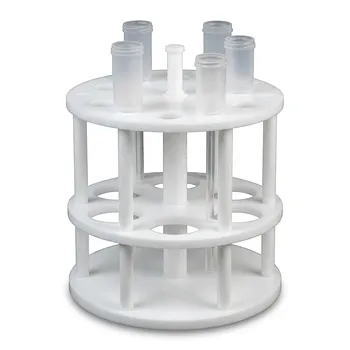
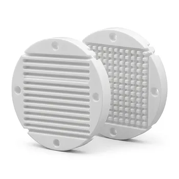
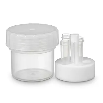
- Custom PFA Microcolumn Racks and PTFE Machined Low Background Corrosion Resistant Laboratory Fixtures
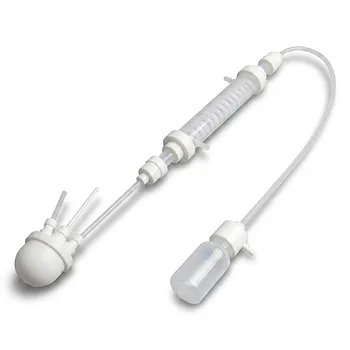
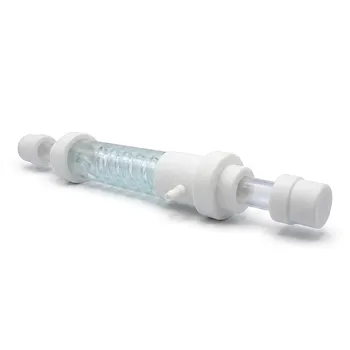
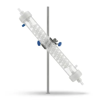
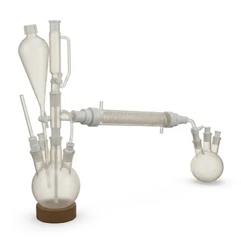
- Corrosion Resistant Hydrogen Fluoride Reflux Apparatus PTFE Flask Condenser Separatory Funnel Collection Bottle High Temperature Laboratory System
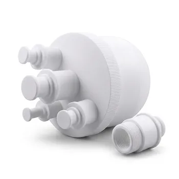
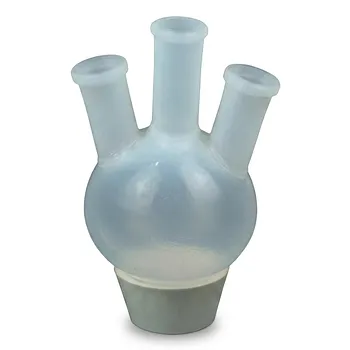
- Large Capacity PTFE Reaction Flask 20L Custom Multi Neck Laboratory Boiling Flask Fluoropolymer Chemical Processing Vessel
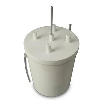
- Custom PTFE Reaction Tank Corrosion Resistant Fluoropolymer Chemical Processing Barrel 10L 20L 30L
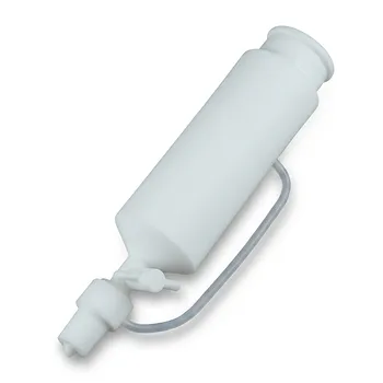
- Custom PTFE Constant Pressure Separatory Funnel 100ml Fluoropolymer Labware for Corrosive Chemical Transfer
People Also Ask
- What other PTFE lab accessories are commonly used? Essential Tools for Chemical Resistance & Purity
- How does high fluorination in perfluorinated polymers improve chemical resistance and thermal stability of lab apparatus? Discover the science behind PTFE and PFA's superior performance.
- How does using chemical-resistant PTFE and PFA laboratory apparatus benefit the purification and isolation of synthesized fluoropolymers? Boost yield and purity with non-stick, low-leach labware.
- What inherent material characteristics of non-melt-processable PTFE make it suitable for manufacturing high-purity laboratory containers and custom-machined apparatus?
- How do extreme temperatures and harsh chemical environments affect PTFE and PFA lab apparatus? Achieve Reliable Performance in Demanding Conditions