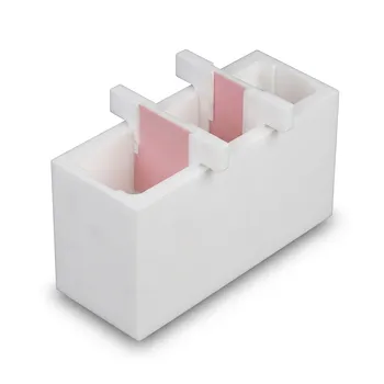
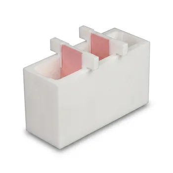
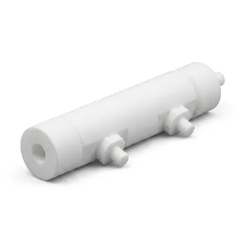
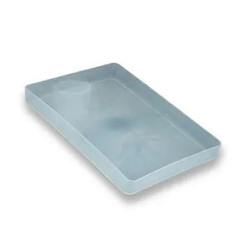
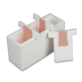
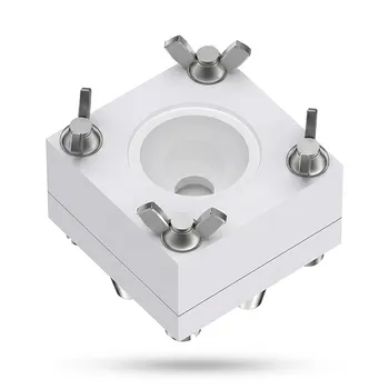
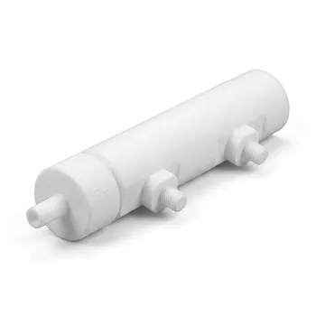
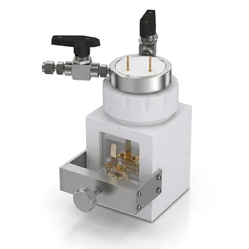
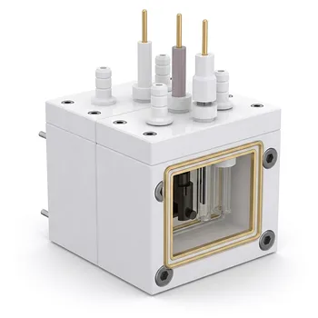
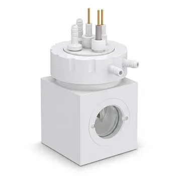
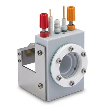
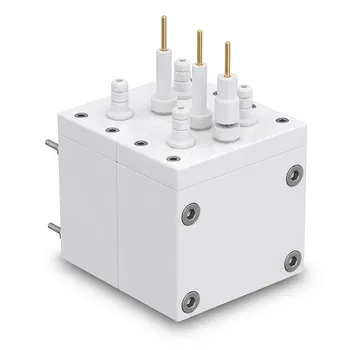
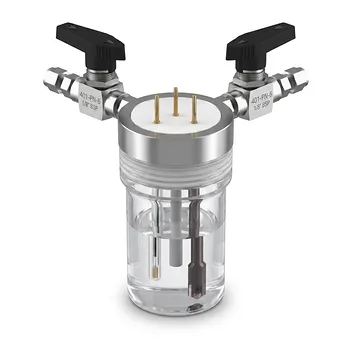
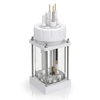
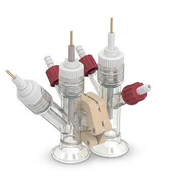
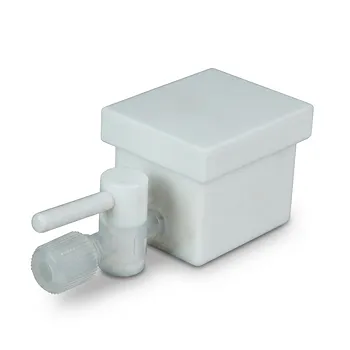
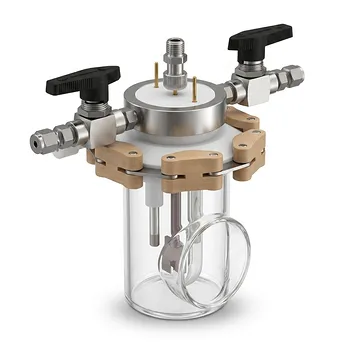
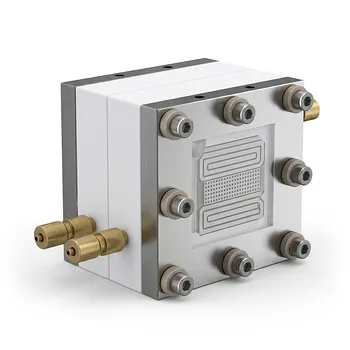
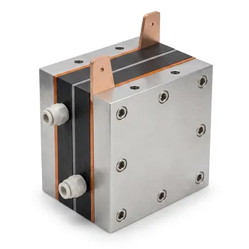
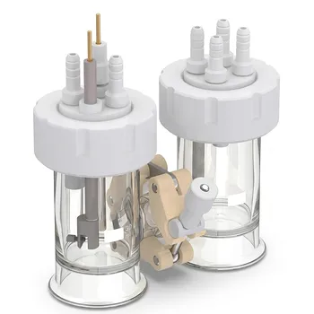
For corrosive fluorinated gases and fluoride-containing electrolytes, the cell should be designed as a chemically isolated, electrically controlled, and thermally managed system. High-purity PTFE or PFA should form the wetted cell body, gas-separation skirts, fluid-transfer paths, and other insulating components exposed to hydrofluoric acid or highly reactive fluorinated species. Dedicated HF and gas connections, reliable sealing, controlled cooling, and careful electrode isolation are critical because standard glass and many metals can corrode rapidly, contaminate the process, or fail under combined chemical and electrical stress.
The central design principle is to prevent the aggressive medium from contacting vulnerable materials while maintaining precise control of gas flow, electrical fields, temperature, and maintenance access. High-purity PTFE and PFA provide the chemical resistance and electrical insulation needed, but the final design must also account for mechanical strength, dimensional stability, sealing, and fluoropolymer-specific limitations.
Start With Chemical Isolation
Use fluoropolymers throughout the wetted path
Every surface exposed to HF, fluoride electrolytes, electrofluorination mixtures, acyl fluorides, or reactive fluorinated gases should be evaluated as part of the wetted path. A chemically resistant cell body is insufficient if a fitting, valve, tubing segment, seal, or fastener introduces a vulnerable material downstream.
High-purity PTFE and PFA are suitable choices for cell bodies, reaction vessels, transfer lines, fittings, valves, and isolation components. Their use reduces corrosion, fluid leakage, and metal-ion contamination during electrochemical and synthesis operations.
Select PTFE and PFA according to the component
PTFE and PFA both offer high chemical inertness and strong electrical insulation, but they should not be treated as interchangeable in every mechanical application. The choice should reflect the component’s fabrication method, operating temperature, dimensional requirements, and expected mechanical loading.
PTFE is well suited to machined cell bodies, insulating holders, gaskets, and chemically exposed parts. PFA is advantageous where melt-processable fluoropolymer construction, formed geometries, or transparent process observation is useful, while still maintaining high chemical resistance.
Eliminate unnecessary dissimilar materials
Metallic inserts, glass windows, conventional elastomers, and adhesive joints can become weak points in an otherwise fluoropolymer-based system. They may corrode, release contaminants, create leak paths, or experience different thermal expansion than the surrounding fluoropolymer.
Where a metal structure is necessary for strength or electrode support, it should be isolated from the aggressive medium through a carefully designed fluoropolymer barrier. The barrier must remain continuous around penetrations, interfaces, and maintenance openings.
Control Gas and Electrolyte Movement
Provide dedicated HF and gas connections
The cell should include purpose-designed HF inlets, gas inlets, gas outlets, and drainage or purge paths. These connections should support controlled flow while minimizing stagnant zones where corrosive residues can accumulate.
Gas outlets should be positioned to prevent trapped pockets and unintended pressure buildup. Inlet and outlet geometry should also reduce the risk of direct gas bypass around a membrane, electrode, or separation skirt.
Isolate gas phases reliably
Gas separation skirts and related internal barriers should be made from high-purity PTFE or PFA when they contact reactive gases or fluoride media. Their purpose is not merely to divide the cell physically; they must preserve phase separation during bubbling, electrolysis, pressure changes, and thermal expansion.
The design should account for the skirt’s attachment method, stiffness, clearances, and exposure to differential pressure. A barrier that distorts during operation can cause gas crossover, liquid leakage, or unintended contact between reaction zones.
Design fluid paths for cleanability
Aggressive chemistries make residue removal and inspection essential. Fluid paths should avoid unnecessary dead legs, sharp internal transitions, and inaccessible cavities that can retain HF or fluorinated reaction products.
Removable membrane and cathode assemblies can reduce maintenance exposure and simplify cleaning. This is particularly important when electrochemical deposits or hazardous reaction products accumulate on electrodes.
Manage Electrical and Electrochemical Stress
Use fluoropolymer insulation deliberately
PTFE and PFA provide high dielectric strength, volume resistivity, and surface resistance. These properties help prevent current leakage, short circuits, and electrical breakdown across the cell housing, electrode holders, and isolation components.
Electrical insulation should be designed around the actual voltage, electrolyte conductivity, component thickness, surface condition, and temperature. Chemical resistance alone does not guarantee electrical reliability if contamination, moisture, sharp edges, or insufficient creepage distances create alternate current paths.
Separate insulation from the active electrode interface
Fluoropolymer components should insulate conductors and define the cell geometry without unintentionally blocking the active electrode area. Poorly positioned holders or skirts can alter current distribution, increase local heating, or create concentration gradients.
Electrode penetrations require particular attention. They should prevent electrolyte and gas leakage while maintaining stable electrical contact and avoiding exposed metal surfaces that can corrode or contaminate the process.
Account for severe electrode environments
The cathode and anode may experience substantially different chemical conditions. Reducing conditions at the cathode and strongly oxidative conditions at the anode can impose different degradation mechanisms on electrodes, seals, supports, and nearby insulation.
Material selection and geometry should therefore be validated separately for each electrode region. A component that remains stable in the bulk electrolyte may still fail near an electrode because of local potential, gas evolution, temperature, or concentration gradients.
Maintain Thermal and Mechanical Stability
Integrate cooling where heat generation is significant
Electrolysis and high-temperature fluorination reactions can produce substantial heat. A cooling jacket or comparable thermal-management feature helps maintain stable process conditions and limits thermal stress on the cell, seals, membranes, and electrical interfaces.
Cooling should be distributed uniformly enough to avoid severe temperature gradients. Localized cooling or heating can cause differential expansion, distortion, leakage, and changes in electrochemical behavior.
Design for fluoropolymer deformation
Fluoropolymers offer excellent chemical resistance but can deform under sustained mechanical load, especially at elevated temperature. PTFE components may exhibit creep, while both PTFE and PFA require appropriate support when used in pressure-containing or dimensionally critical assemblies.
Flanges, threaded interfaces, membrane supports, and sealing surfaces should be designed with these characteristics in mind. Avoid relying on a thin unsupported fluoropolymer wall to maintain alignment or sealing force over long operating periods.
Preserve dimensional stability
The cell must maintain electrode spacing, membrane position, gas separation, and seal compression across the expected temperature range. Thermal expansion differences between fluoropolymers, electrodes, fasteners, and support structures can shift these relationships during operation.
Design features such as compliant seals, controlled clearances, supported barriers, and symmetric thermal paths help accommodate expansion without losing alignment or containment.
Protect Purity and Measurement Quality
Minimize trace contamination
Metal-ion contamination can alter reaction chemistry, compromise product purity, and interfere with electrochemical measurements. High-purity fluoropolymer construction reduces the number of reactive or extractable materials in contact with the process.
Purity control must include fittings, tubing, valves, seals, machining residues, cleaning agents, and assembly hardware. The cell should be cleaned and conditioned using procedures compatible with the intended chemistry.
Reduce unwanted electrical interference
High dielectric strength and high resistivity help isolate the measurement circuit from conductive or corrosive electrolytes. This supports stable electrochemical measurements and reduces the risk of signal distortion caused by leakage currents.
Geometry also matters. Cable routing, electrode spacing, shielding, and the placement of insulating barriers should be considered together, particularly in high-voltage or sensitive analytical systems.
Validate the complete assembly
Material certificates for the fluoropolymer are useful, but they do not validate the entire cell. The assembled system should be checked for leakage, electrical isolation, dimensional stability, gas crossover, and compatibility under representative temperature and chemical conditions.
Testing should include the interfaces most likely to fail: seals, penetrations, tubing connections, membrane supports, and transitions between fluoropolymer and any unavoidable non-fluoropolymer component.
Understanding the Trade-offs
Chemical resistance does not remove mechanical risk
PTFE and PFA can withstand aggressive chemical environments, but they are not automatically suitable for every pressure, load, or temperature condition. Excessive stress, unsupported spans, thermal cycling, and over-compressed seals can still produce deformation or leakage.
The cell should use external supports or containment structures where needed, while preserving fluoropolymer isolation from the corrosive medium.
High purity can limit material and manufacturing choices
Avoiding metals, glass, conventional elastomers, and adhesives may increase fabrication complexity and cost. Custom machining, forming, cleaning, and inspection also become more important when the cell must maintain tight tolerances and low contamination levels.
That added effort is justified when corrosion, contamination, or hazardous leakage would compromise the process. It should nevertheless be addressed early in the design so that replacement parts and maintenance procedures remain practical.
Fluoropolymer insulation can complicate heat removal
Fluoropolymers are effective electrical insulators, but the cell may require deliberate thermal design to remove heat from the reaction zone. A fully insulating structure can make temperature control more difficult if the cooling path is poorly placed.
Cooling jackets, thermally conductive external supports, and strategically located temperature sensors can help manage this limitation without exposing the chemistry to vulnerable materials.
Sealing is a system problem
A chemically resistant seal material can still fail if the joint design allows creep, uneven compression, thermal movement, or mechanical misalignment. Leakage prevention depends on the flange geometry, surface finish, compression method, fasteners, and inspection procedure as much as on the polymer itself.
Particular care is required around removable membranes, electrode assemblies, and gas connections because these areas combine frequent service with difficult containment requirements.
How to Apply This to Your Project
The most reliable design process evaluates chemistry, electrical conditions, gas handling, temperature, mechanics, purity, and maintenance as one integrated system.
- If your primary focus is corrosion resistance: Use high-purity PTFE or PFA for the complete wetted path, including the cell body, skirts, tubing, fittings, valves, and seals, while isolating any unavoidable metal or glass.
- If your primary focus is gas and HF containment: Provide dedicated inlets and outlets, eliminate stagnant regions, support gas-separation skirts, and test every penetration and removable interface for leakage and crossover.
- If your primary focus is electrochemical measurement quality: Use fluoropolymer insulation to control leakage and electrical breakdown, then verify electrode geometry, surface cleanliness, grounding, and isolation under the actual electrolyte conditions.
- If your primary focus is long-term reliability: Design for creep, thermal expansion, electrode asymmetry, seal compression, and dimensional stability across the full operating range.
- If your primary focus is safe maintenance: Make membranes and cathode assemblies removable, provide accessible cleaning paths, and minimize technician exposure to retained corrosive or hazardous products.
A successful custom fluoropolymer electrochemical cell is not simply corrosion-proof; it preserves containment, purity, electrical control, thermal stability, and maintainability throughout the complete operating cycle.
Summary Table:
| Aspect | Critical Design Principle | Material/Component Choice |
|---|---|---|
| Chemical Isolation | Use fluoropolymers throughout wetted path; eliminate dissimilar materials | High-purity PTFE/PFA for body, skirts, fittings, seals |
| Gas & Electrolyte Control | Dedicated connections, avoid stagnant zones, reliable gas-phase isolation | PTFE/PFA gas skirts, optimized inlet/outlet geometry |
| Electrical Insulation | High dielectric strength, creepage distances, separate insulation from electrode | PTFE/PFA insulators, careful electrode penetration design |
| Thermal Management | Integrate cooling, account for fluoropolymer creep and thermal expansion | Cooling jacket, supported fluoropolymer walls, symmetric thermal paths |
| Purity & Measurement | Minimize metal contamination, prevent leakage currents | High-purity fluoropolymers, cleanable fluid paths, validated assembly |
At KINTEK, we specialize in custom PTFE/PFA electrochemical cells that deliver unmatched corrosion resistance and purity. Our engineering team can design, machine, and assemble complete cell systems, from laboratory-scale to high-volume production, ensuring your process is safe, reliable, and efficient. Contact us today to discuss your requirements and receive a tailored solution. Request a Consultation
Related Products
- Corrosion Resistant PTFE Electrochemical Cell for New Energy Research Inert Insulating Customizable Lab Reaction Vessel
- Square PTFE Electrochemical Cell for Silicon Wafer Processing and Hydrofluoric Acid Resistance in Semiconductor and New Energy Research
- Custom PTFE Electrolytic Cell Corrosion Resistant Low Background Reaction Vessel with Inlet Outlet Ports
- Customizable PFA Square Tray Corrosion Resistant High Temperature Large Petri Dish Electrolytic Cell
- White PTFE Electrolytic Cell with Movable Slider and Insulated Lid for Fluorine Corrosion Resistance
People Also Ask
- How do custom PTFE electrochemical cells improve the accuracy of stability testing for alkaline catalysts compared to glass cells?
- How does the hydrophobicity of PTFE benefit electrochemical measurements? Enhance Stability and Precision in Your Lab
- What makes PTFE an ideal construction material for custom electrochemical cells and electronic analytical instrumentation housings? Discover superior chemical resistance and electrical insulation
- Why must seawater electrolysis test cells have high corrosion resistance? Protect catalyst stability & data accuracy.
- What are the key steps for structural integrity in molded PTFE lab reaction vessels? Master fine powder processing.