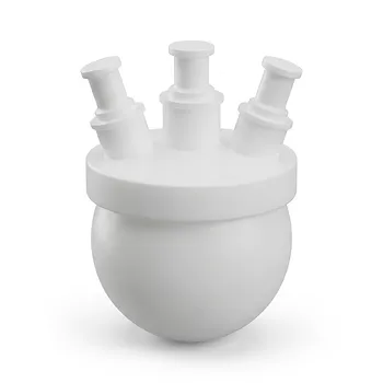
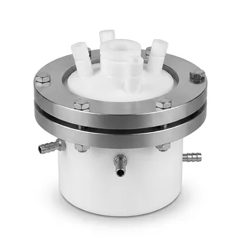
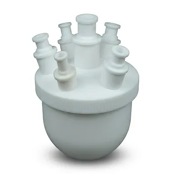
The process requires a tightly integrated high-temperature plasma reactor and quench system. For noble-gas plasma-assisted TFE synthesis, pentafluoroethane (CF₃CHF₂) must be introduced into an argon thermal plasma, heated to approximately 2,000 K, and then quenched to about 800 K within 0.001 to 0.1 seconds. Reactor performance depends on accurately controlling plasma power, gas velocity, residence time, and cooling capacity; in the referenced process, increasing power from 4 kW to 8 kW raised TFE in the product gas from 51.5% to 75.8% and removed detectable unreacted starting material.
The decisive requirement is not simply reaching the pyrolysis temperature; it is preventing the reaction mixture from remaining hot long enough for secondary reactions and decomposition. The vessel must therefore combine controlled argon-plasma heating with rapid, high-capacity thermal quenching.
What the Reaction Vessel Must Accommodate
High-temperature plasma heating
The vessel must couple effectively to an argon thermal plasma capable of heating the CF₃CHF₂-containing feed near 2,000 K. Plasma power must be controllable because the reported change from 4 kW to 8 kW substantially affected conversion and TFE concentration.
A suitable design must maintain stable power delivery while handling a reactive fluorocarbon environment at extreme temperature. The plasma zone, feed point, and downstream quench zone should be treated as one integrated reaction system.
Controlled reactant introduction
The CF₃CHF₂ and argon streams must enter the plasma region at a sufficiently high velocity to produce consistent mixing and limit uncontrolled residence time. High-velocity gas introduction is specifically identified as a design requirement for the thermal reactor.
Feed delivery must also be synchronized with plasma power. Changes in flow rate alter residence time, heat loading, reactant concentration, and the rate at which the mixture reaches the quench section.
Short, defined reaction residence time
The reaction mixture should remain at the high pyrolysis temperature only long enough to generate TFE. The process window requires extremely rapid movement from the approximately 2,000 K reaction zone to the cooling stage.
A specialized vessel therefore needs a defined hot-zone geometry and a predictable gas-flow path. Dead zones, recirculation regions, or poorly controlled expansion areas could increase exposure to high temperature and encourage secondary reactions.
Why Rapid Quenching Is Essential
Quenching must occur within milliseconds to tenths of a second
After pyrolysis, the product gas must be cooled from approximately 2,000 K to 800 K within 0.001 to 0.1 seconds. This is the central thermal requirement of the process.
The quench system must have enough heat-transfer capacity to remove the reaction heat at the actual gas throughput. A cooling jacket or comparable rapid-cooling arrangement should begin immediately downstream of the plasma zone, with minimal uncooled volume between reaction and quench.
The cooling system controls product preservation
Rapid cooling helps preserve the desired TFE product by reducing the time available for further high-temperature reactions. It is therefore a product-selectivity requirement, not merely a mechanical temperature-control feature.
Cooling performance should be assessed using measured gas temperatures and residence times rather than relying only on jacket set points. The relevant temperature is the reacting gas temperature, particularly during the transition from the plasma zone into the quench section.
The vessel must avoid thermal gradients
Localized hot regions can create inconsistent conversion and increase the risk of unwanted decomposition. The reactor and quench design should minimize stagnant regions and provide uniform exposure of the gas stream to the cooling system.
This is especially important because TFE is also a highly energetic polymerizable monomer. The process must prevent hot product gas from accumulating or remaining uncontrolled after formation.
Operating Controls That Determine Yield
Plasma power
Plasma power is a primary process variable. The reference data show that increasing power from 4 kW to 8 kW increased TFE yield in the product gas from 51.5% to 75.8% and eliminated unreacted CF₃CHF₂ under the reported conditions.
The result should not be interpreted as a universal optimum. The appropriate power level depends on feed rate, gas composition, reactor geometry, and cooling capacity, so power must be established together with the material and energy balance for the specific vessel.
Gas composition and dilution
Argon serves as the noble-gas plasma medium and can also influence heat transport and reactant concentration. Feed composition should be controlled closely because excessive reactant concentration can increase heat release, alter plasma behavior, and overload the quench system.
Supplementary process knowledge shows that inert dilution and reduced partial pressure can favor TFE formation in conventional pyrolysis systems by shifting gas-phase equilibrium toward products with greater mole volume. That principle may inform process development, but it does not replace validation for the argon-plasma route.
Pressure
Pressure affects gas density, residence time, heat transfer, and equilibrium behavior. Because the supplied reference does not specify the operating pressure for the argon-plasma process, pressure should be treated as a parameter requiring experimental determination rather than assigned a fixed value from the conventional chlorodifluoromethane route.
The pressure-control system should provide stable operation during startup, steady state, quenching, and shutdown. Pressure excursions can change the thermal profile and compromise the intended residence-time window.
Product-gas handling
The outlet must remove TFE rapidly from the hot zone and direct it into controlled downstream handling. The system should prevent product-gas holdup, uncontrolled recirculation, and exposure of accumulated monomer to hot surfaces.
Because TFE can polymerize violently under unfavorable thermal conditions, downstream equipment should be designed around rapid removal and temperature control rather than simple collection of a hot gas mixture.
Understanding the Trade-offs
Higher power can improve conversion but increase heat load
The reported increase from 4 kW to 8 kW improved TFE yield and conversion. However, higher power also increases the thermal duty imposed on the reactor, quench jacket, downstream piping, and control system.
A power increase is therefore appropriate only when the gas-flow path and cooling system can remove the additional heat without creating hot spots or extending the effective high-temperature residence time.
Fast flow improves throughput but narrows the control window
High-velocity introduction supports rapid transport through the plasma and toward the quench zone. Excessive velocity, however, can reduce mixing or cause unstable plasma-feed interaction.
The design must balance velocity, mixing, residence time, and pressure drop. These variables should be evaluated together rather than optimized independently.
TFE formation creates a downstream hazard
TFE polymerization is exceptionally exothermic, releasing approximately 172.0 kJ/mol. If heat is not removed effectively, localized hot spots can trigger violent deflagration or explosive decomposition of unreacted TFE into carbon and carbon tetrafluoride.
The thermal reactor, quench section, and product-handling system must therefore be designed as a continuous hazard-control boundary. Preventing accumulation and maintaining temperature control downstream are as important as achieving conversion in the plasma zone.
Conventional-route data are not direct operating instructions
The conventional CHClF₂ route uses a different chemistry and can generate HCl and chlorinated materials. Its reported equilibrium behavior, reduced-pressure operation, and dilution effects provide useful context but should not be transferred directly to the argon-plasma process.
The noble-gas route is attractive because it avoids chlorinated feed impurities and HCl formation associated with that commercial pathway, but its operating envelope must be established specifically for CF₃CHF₂ plasma pyrolysis.
Making the Right Choice for Your Goal
The vessel and process should be specified against the intended operating priority:
- If your primary focus is high TFE conversion: Provide controllable plasma power, consistent CF₃CHF₂/argon delivery, and a residence-time-controlled hot zone; the reference result indicates that 8 kW produced higher TFE content and no remaining starting material under its tested conditions.
- If your primary focus is product selectivity: Prioritize immediate quenching from approximately 2,000 K to 800 K within 0.001 to 0.1 seconds, with minimal dead volume between the plasma and cooling sections.
- If your primary focus is reactor safety: Design the entire hot zone, quench jacket, outlet, and downstream system to prevent hot spots and TFE accumulation, recognizing the high heat of TFE polymerization.
- If your primary focus is process scale-up: Recalculate gas residence time, plasma power density, pressure behavior, and cooling duty for the larger flow rate rather than scaling power alone.
- If your primary focus is a chlorinated-impurity-free route: Use the CF₃CHF₂/argon plasma pathway while separately validating materials compatibility, emissions control, and downstream product handling for the fluorocarbon mixture.
A reliable TFE plasma-synthesis vessel is defined by coordinated power input, controlled gas transport, and near-immediate quenching, with safety controls extending through the entire product-gas path.
Summary Table:
| Requirement | Critical Value/Feature | Impact on Synthesis |
|---|---|---|
| Plasma Heating | Argon plasma; controllable power (4-8 kW) | Drives pyrolysis of CF₃CHF₂ to TFE |
| Pyrolysis Temperature | ~2,000 K | Initiates TFE formation |
| Quench Rate | 2,000 K to 800 K in 0.001–0.1 s | Prevents secondary reactions, preserves TFE |
| Residence Time | Defined, short (controlled by gas velocity and geometry) | Limits decomposition, enhances selectivity |
| Plasma Power Increase | From 4 kW to 8 kW | Increases TFE from 51.5% to 75.8%; eliminates unreacted feed |
| Gas Velocity | High-velocity introduction | Ensures mixing, limits hot-zone residence time |
| Cooling Capacity | High-capacity, minimizes dead volume | Maintains product integrity, prevents hot spots |
| Feed Composition | Controlled Ar/CF₃CHF₂ ratio | Influences heat transfer and partial pressure |
| Pressure Control | Stable; not predefined | Affects residence time and equilibrium |
| Safety | Handle TFE's exothermic polymerization (ΔH = -172 kJ/mol) | Prevents hazardous decomposition |
Ready to elevate your TFE synthesis capabilities? At KINTEK, we specialize in high-performance fluoropolymer solutions. Our PTFE and PFA custom-machined components and labware ensure precision, purity, and safety for your most demanding thermal processes. Partner with us to optimize your reaction vessels for maximum yield and safety. Contact us today to discuss your specific requirements!
Related Products
- Custom PTFE Continuous Reaction Bottles Virgin Fluoropolymer High Purity Low Background Synthesis Vessels
- Custom Multi Neck PTFE Round Bottom Flask for Chemical Synthesis and High Purity Laboratory Research
- High Pressure Custom TFM Reactor Stainless Steel Outer Vessel PTFE Inner Cup for Corrosive Synthesis
- Laboratory Hydrothermal Synthesis Autoclave Reactor PTFE PPL Lined High Temperature High Pressure Explosion Proof Reaction Vessel
- High Purity PTFE Multi Neck Reaction Flask for Corrosive Chemical Processing and Custom Industrial Laboratory Synthesis
People Also Ask
- What reaction vessel and fluid handling considerations are necessary for living cationic polymerization of fluorinated monomers involving Lewis acid catalysts? Key design and safety tips
- Ion Activation Reaction Vessel Requirements: Why PTFE is Critical for Membrane Performance
- How do perfluorinated solvent environments influence the selection of reaction vessels and fluid handling components in nonaqueous emulsion polymerizations? Choose fluoropolymer materials.
- Why are high-purity PTFE or PFA reaction vessels recommended for the synthesis of PANI-TiC hybrid materials? - Guide
- Why are fluoroplastic (PTFE) reaction vessels recommended for Methylene Blue (MB) adsorption kinetic experiments?