The key mechanism is fibril bridging. In PTFE crystalline phases I and IV, high stress near a crack tip causes nearby crystalline domains to uncoil, plastically deform, and align with the principal stress direction. These drawn molecular structures form strong microscopic fibrils that bridge the crack faces, dissipate energy, and slow crack growth rather than allowing rapid brittle propagation.
PTFE resists rapid crack propagation because strain-induced fibrils bridge the developing crack. Their plastic deformation and crack-tip shielding absorb energy and reduce the stress driving the crack forward.
How PTFE Arrests Crack Growth
Microvoids form at highly stressed regions
A crack tip concentrates stress into a very small volume. Under sufficient strain, microvoids can form in the material surrounding that tip.
These voids do not automatically produce catastrophic failure because the adjacent crystalline regions can deform and reorganize.
Crystalline domains uncoil and align
The local stress causes PTFE’s crystalline structures to uncoil, draw out, and align along the direction of principal stress.
This alignment converts portions of the polymer into elongated, load-bearing structures instead of leaving the crack tip surrounded by undeformed material.
Fibrils bridge the crack plane
The drawn structures develop into microscopic fibrils that span the crack plane. They act like tiny reinforcing ligaments connecting the two sides of the developing crack.
As the crack attempts to open, these fibrils carry part of the load and resist further separation.
Why Fibril Bridging Slows Propagation
Energy is dissipated through plastic deformation
Fibril formation requires localized molecular rearrangement and plastic deformation. That process consumes mechanical energy that would otherwise contribute directly to extending the crack.
The result is a slower, more stable crack-growth process under strain.
The crack tip is shielded
The fibrils reduce the effective stress intensity at the crack tip by carrying load behind the advancing front. This crack-tip shielding makes it more difficult for the crack to continue propagating rapidly.
The mechanism is particularly important in PTFE components exposed to sustained mechanical or pressure-related strain, including fittings, seals, and reaction vessels.
Failure becomes less brittle
Instead of separating suddenly through an unstressed, brittle path, the material develops a deformable zone around the crack. This gives PTFE a degree of resistance to rapid fracture at ambient and elevated temperatures in the cited crystalline phases.
Understanding the Trade-offs
Fibril bridging is a resistance mechanism, not immunity
Fibrils slow crack growth, but they do not make PTFE immune to cracking or failure. Sufficient stress, prolonged loading, defects, temperature, chemical environment, or unfavorable geometry can still drive damage forward.
Local deformation can precede visible failure
Because the mechanism depends on molecular drawing and plastic deformation, the component may undergo localized damage before a macroscopic crack becomes obvious. Inspection and appropriate design margins therefore remain important.
Performance depends on service conditions
The effectiveness of fibril bridging depends on the material’s microstructure and the applied strain state. PTFE components should not be treated as universally damage-tolerant simply because this mechanism exists.
Applying the Mechanism to PTFE Components
The practical implication is that PTFE’s crack resistance comes from controlled microstructural deformation ahead of the crack, not from preventing all deformation.
- If your primary focus is crack resistance: Recognize fibril bridging and crack-tip shielding as the main mechanisms that retard rapid crack propagation in PTFE.
- If your primary focus is component design: Account for stress concentrations, sustained strain, temperature, defects, and service environment rather than relying on fibril formation alone.
- If your primary focus is failure analysis: Look for evidence of localized drawing, microvoid formation, and fibrillar structures around the crack path.
PTFE resists rapid crack growth by converting concentrated crack-tip stress into energy-absorbing fibril formation and crack-tip shielding.
Summary Table:
| Mechanism | Description | Benefit |
|---|---|---|
| Microvoid formation | Voids form at crack tip but are stabilized by adjacent crystalline regions | Prevents catastrophic failure |
| Crystalline alignment | Uncoiling and aligning of polymer chains along stress direction | Transforms material into load-bearing structures |
| Fibril bridging | Drawn fibrils span the crack faces, acting as reinforcing ligaments | Carries load and resists separation |
| Energy dissipation | Plastic deformation consumes energy | Slows crack growth |
| Crack-tip shielding | Fibrils reduce stress intensity at the crack tip | Makes propagation more difficult |
| Less brittle failure | Deformable zone around crack | Increases resistance to rapid fracture |
Enhance your PTFE components with KINTEK's high-performance fluoropolymer products. Our PTFE and PFA labware, fluid handling systems, and custom CNC machined parts are engineered to withstand crack propagation. Whether you need standard beakers, high-purity analysis instruments, or complex electrochemical cells, our expertise ensures reliability. Contact us today to discuss your requirements and benefit from our OEM/ODM support, fast delivery, and supply reliability. For distributors, we offer competitive margins and full certifications.
Related Products
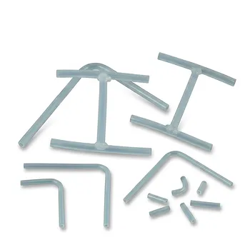
- High Performance PFA Coiled Spring Tubing and Custom PTFE Fabrication Services with Welded Fittings and Precision Bent Components
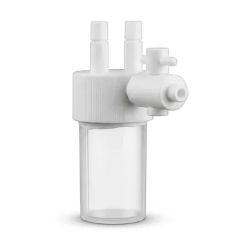
- Custom PTFE Reaction Lid with Integrated Valve and Fitting Corrosion Resistant No Leaching PFA FEP Bottle Cap System
- High Purity PTFE Corrosion Resistant Reaction Vessel with Luer Fittings and Caps for Trace Analysis
- Custom Polytetrafluoroethylene White Syringe Corrosion Resistant Teflon Plastic Injector Threaded Luer Fitting Compatible
- Custom Polytetrafluoroethylene PTFE Constant Pressure Dropping Funnel Corrosion Resistant Fluid Control Assembly with Conversion Stopper Compatibility
People Also Ask
- What are the technical advantages of high-precision PFA tubing in MXene production? Maximize Purity and Yield.
- What technical advantages do PFA tubing and fittings offer? Master Precision Fluid Transfer and Flow Chemistry
- What are the technical advantages of high-quality PFA tubing? Achieve Ultimate Purity and Precision in Fluid Handling
- What are the key benefits of PTFE in custom fabrication? Unlock Performance in Extreme Conditions
- What fabrication services are available for PTFE? Shearing, Stamping, Laser Cutting, Molding & Machining