PTFE sample holders generally preserve the film’s crystal structure and measured chemical purity compared with glass, while producing a small difference in optical response. For semiconductor thin films such as PbS:Th deposited on GaAs, films grown with PTFE holders retain the same crystalline phase and major XRD orientations as films grown with glass holders. Photoluminescence measurements show a slight blue shift for films deposited using glass, whereas PTFE-grown films maintain the baseline emission more consistently.
PTFE holders are a chemically inert alternative that can improve optical and photo-response reproducibility without materially changing crystal structure or detected Si and O impurity concentrations under the reported conditions.
How Holder Material Affects Optical Properties
Photoluminescence Emission
The clearest difference between the holder materials appears in photoluminescence (PL). Films synthesized with glass holders show a minor blue shift in emission wavelength relative to films grown with PTFE holders.
This shift does not necessarily indicate a different bulk crystal phase. It more likely reflects small changes in surface chemistry, defect states, interfacial conditions, or film growth kinetics caused by interaction between the deposition solution and the holder.
Optical Stability
PTFE-grown films maintain their baseline PL emission more consistently. The inert fluoropolymer is less likely to interact with strongly acidic or alkaline chemical bath solutions during deposition.
Glass can experience limited surface interaction or leaching under aggressive chemical conditions. Even when the resulting chemical changes are too small to alter the main film structure, they may influence optically active defects or recombination pathways.
Photo-Response Behavior
The supplementary evidence also associates PTFE holders with more consistent transient photocurrent behavior. Films grown with PTFE do not show the same rapid signal decay reported for films deposited using glass holders.
This suggests that holder-related chemical interactions can affect not only the PL peak position but also the stability of carrier generation and transport under illumination.
Why the Crystal Structure Remains Similar
XRD Phase Identification
X-ray diffraction indicates that the semiconductor films retain the same crystalline phase with either holder material. For PbS-based films, the characteristic (111), (220), and (222) reflections remain present.
Therefore, replacing glass with PTFE does not appear to change the fundamental phase formed during deposition under the reported conditions.
Preferred Orientations
The major diffraction peak orientations are also consistent between the two holder types. This means that any holder-dependent effect is small relative to the factors that determine crystal formation and texture.
Substrate properties, deposition chemistry, temperature, precursor concentration, and growth time are likely more influential in determining the film’s dominant crystallographic orientation.
Structural Integrity
PTFE holders preserve film structural integrity while reducing the possibility of chemical interaction with the deposition bath. Their primary advantage is therefore process stability and reproducibility, rather than a deliberate change in lattice structure.
A similar XRD pattern should not be interpreted as proof that the films are identical in every microscopic respect. Defect density, strain, grain boundaries, or surface morphology may still differ even when the main diffraction peaks are unchanged.
What Happens to Elemental Impurities
Silicon and Oxygen Measurements
Secondary Ion Mass Spectrometry depth profiling shows no significant difference in silicon (Si) or oxygen (O) levels across the film and interface region for PTFE and glass holders.
Based on these measurements, PTFE does not produce a measurable reduction in those specific impurities compared with glass in the investigated samples.
Chemical Inertness
PTFE is chemically inert toward many deposition environments, making it less likely to contribute species through dissolution, corrosion, or surface reaction. This is valuable when the objective is to maintain reproducible high-purity growth.
However, chemical inertness does not mean that PTFE can introduce no contamination under any circumstances. Machining residues, surface deposits, handling, cleaning quality, and the specific deposition chemistry must still be controlled.
Interpreting “No Significant Difference”
The absence of a significant Si or O difference is tied to the elements measured, the detection limits, and the tested process conditions. It should not be generalized automatically to every possible impurity or deposition system.
PTFE’s practical benefit is that it reduces a plausible source of process variability, even when SIMS does not show a large change in the selected impurity profiles.
Understanding the Trade-offs
PTFE Improves Chemical Compatibility
PTFE is well suited to deposition baths that are strongly acidic, alkaline, or otherwise chemically aggressive. Its resistance to these environments helps maintain stable holder surfaces over repeated depositions.
This can support more reproducible optical emission and photo-response behavior between batches.
Glass Is Convenient but Less Inert
Glass is inexpensive, widely available, and easy to inspect. Its limitation is that prolonged exposure to reactive solutions can produce minor surface reactions or leaching, depending on the glass composition and bath chemistry.
Those effects may be subtle: the film can retain the same XRD pattern while showing a measurable PL shift or less stable photoconductivity.
PTFE Requires Better Process Control
PTFE holders must be properly machined, cleaned, and conditioned before use. Poor cleaning can transfer residues to the deposition bath, and soft fluoropolymer surfaces can be damaged or retain deposits if handled incorrectly.
The holder material should therefore be evaluated as part of the complete process, not treated as an isolated guarantee of purity.
Optical Differences Need Independent Verification
A small PL blue shift is evidence of an optical difference, but PL alone does not identify its cause. To distinguish defect changes from composition, strain, thickness, or morphology effects, PL should be interpreted alongside XRD, SIMS, microscopy, and electrical measurements.
Making the Right Choice for Your Goal
The best holder depends on whether the priority is chemical compatibility, optical repeatability, structural comparison, or impurity control.
- If your primary focus is optical reproducibility: Use properly cleaned PTFE holders and verify PL peak position and photoconductivity across repeated depositions.
- If your primary focus is crystal structure: Either holder can produce the same major PbS crystalline phase and orientations under comparable conditions, but confirm this with XRD for each process.
- If your primary focus is elemental purity: PTFE is a strong choice for minimizing holder-solution interaction, while using SIMS or another suitable method to verify the impurities relevant to your application.
- If your primary focus is process cost and convenience: Glass may remain practical for benign chemistries, but PTFE is preferable when aggressive solutions or batch-to-batch optical stability are important.
Choosing PTFE provides a more chemically stable deposition environment while preserving the film’s principal crystal structure and measured elemental purity.
Summary Table:
| Aspect | PTFE Holder | Glass Holder |
|---|---|---|
| Optical Properties | Baseline PL emission, stable photo-response | Slight blue shift, less stable photo-response |
| Crystal Structure | Same XRD pattern, same orientations | Same XRD pattern, same orientations |
| Elemental Impurities | No significant difference in Si, O | No significant difference in Si, O |
| Chemical Inertness | High, resistant to aggressive baths | Lower, possible leaching |
| Process Suitability | Best for optical reproducibility and aggressive chemistries | Convenient, low cost |
For high-purity PTFE sample holders and custom labware that enhance reproducibility in semiconductor deposition, trust KINTEK's expertise. Our PTFE/PFA products ensure chemical inertness and consistent results. Contact us today to discuss your requirements and benefit from our advanced manufacturing capabilities.
Related Products
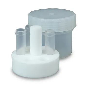
- High Purity Corrosion Resistant PTFE Sample Injection Tube Rack 6 Hole Compatible with Laboratory Reaction Vessels
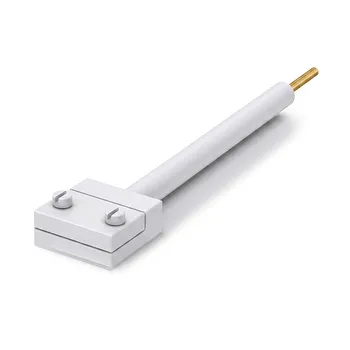
- PTFE Electrochemical Electrode Holder for Thickened Samples with Platinum Contact Sheet
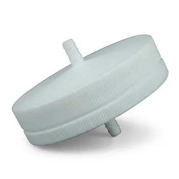
- PTFE Membrane Filter Holder for Aerosol Environmental Monitoring and Low Concentration Particulate Matter Sampling Chemical Resistant Air Quality Analysis Component
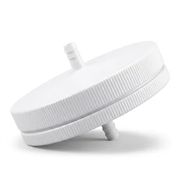
- PTFE Filter Membrane Holder for Hydrogen Chloride and Water Filtration 90mm Environmental Sampling Clamp Customizable
- PTFE Filter Membrane Holder 47mm Leak Proof Corrosion Resistant Environmental Sampling Unit Customizable
People Also Ask
- What surface chemical species and binding energy signatures are detected on PTFE fluoropolymer sample holders during XPS analysis? Key insights for accurate calcium detection.
- How does using fluoropolymer (PTFE) sample holders compare to glass holders in affecting the optical and photoelectric properties of thin films during chemical bath deposition? Discover the Impact
- How does paste extrusion impart structural integrity to unsintered PTFE lab tubing?
- What structural components are typically found in a high-purity PTFE wafer cleaning rack? Optimize Your Cleaning Process
- Why is PTFE considered an ideal material for high-purity laboratory vessels and fluid transfer components handling harsh acids and corrosive gases?