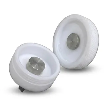
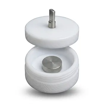
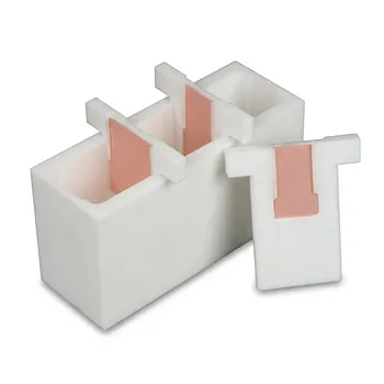
The structural design of a PTFE battery clamp minimizes electrical noise and edge effects by completely encasing the internal conductor within a thick, insulating PTFE body. This architecture ensures that only a precise, intended contact point is exposed to the electrode, effectively enforcing a defined electroactive area. By isolating the conductor from the surrounding environment, the design eliminates stray capacitance and field distortions that typically interfere with sensitive electrochemical measurements.
The PTFE battery clamp achieves high-fidelity signal capture by utilizing a geometry that isolates the conductor and leverages PTFE’s extreme dielectric properties. This combination prevents the "leakage" of electrical signals and ensures that the data collected reflects only the specific interaction at the electrode interface.
Precision Through Geometric Isolation
Defining the Electroactive Area
The clamp's primary structural feature is the total encapsulation of the internal conductor. By leaving only a specific contact point open, the design prevents the electrolyte or the rest of the sample from interacting with the conductor at unintended locations. This creates a mathematically defined electroactive area, which is essential for calculating current density and other critical metrics accurately.
Eliminating Edge Effects and Field Distortions
Edge effects occur when electrical field lines concentrate at the corners or edges of a conductor, leading to non-uniform current distribution. The thick PTFE shielding acts as a dielectric barrier that smooths these field lines and prevents "fringe" interactions. This results in a more uniform electrical environment, which is vital for obtaining reproducible results across different test batches.
Suppressing Stray Capacitance
Stray or parasitic capacitance often introduces "ghost" signals that distort high-frequency measurements. The structural separation provided by the PTFE body minimizes the proximity of the conductor to other conductive elements or the electrolyte. This reduces the capacitive coupling between the measurement system and its environment, leading to a much higher signal-to-noise ratio.
Leveraging PTFE Material Properties
The Role of High Volume Resistivity
PTFE possesses a volume resistivity exceeding 10^18 Ω·cm, making it one of the most effective insulators available. This property ensures that the clamp body itself does not facilitate surface leakage currents or short circuits between the electrode and the counter electrodes. By preventing these stray currents, the structural design ensures that 100% of the measured signal originates from the intended contact point.
Dielectric Strength and Signal Integrity
With a dielectric strength of approximately 60 MV/m, the PTFE body can withstand significant electrical stress without breaking down. Its low dielectric constant (2.1) is particularly important for Impedance Spectroscopy (EIS), as it prevents the clamp from introducing its own frequency-dependent signatures. This allows researchers to capture "clean" data that represents the true electrochemical behavior of the battery chemistry.
Hydrophobicity and Maintenance
The structural design also considers the physical interaction with the sample, utilizing PTFE's low surface energy. The hydrophobic nature of the material prevents the adhesion of active material powders and electrolyte residues. This non-stick surface facilitates rapid, residue-free insertion of electrodes, which minimizes experimental downtime and prevents cross-contamination between tests.
Understanding the Trade-offs and Limitations
Mechanical Deformation and Cold Flow
While PTFE is an excellent insulator, it is a relatively soft polymer subject to creep or "cold flow" under sustained pressure. If the clamp is over-tightened during structural assembly, the PTFE body may slightly deform over time, potentially altering the defined contact area. Users must calibrate their tightening force to ensure a secure connection without compromising the geometric integrity of the insulation.
Temperature Constraints
Although PTFE is stable at high temperatures compared to many plastics, it does have a finite thermal limit. In extreme high-temperature battery testing, the structural expansion of the PTFE body might differ from the internal metal conductor. This differential thermal expansion can occasionally create microscopic gaps where electrolytes might seep, potentially re-introducing noise if the seal is compromised.
Making the Right Choice for Your Goal
How to Apply This to Your Project
To maximize the benefits of a PTFE battery clamp, align your usage with your specific analytical requirements:
- If your primary focus is Impedance Spectroscopy (EIS): Prioritize the clamp’s low dielectric constant to ensure that high-frequency data remains free from parasitic capacitance.
- If your primary focus is High-Precision Voltammetry: Rely on the defined electroactive area enforced by the PTFE shielding to ensure accurate current density calculations.
- If your primary focus is High-Throughput Testing: Leverage the non-stick, hydrophobic properties of the PTFE body to facilitate fast cleaning and sample swapping between batches.
The integration of advanced geometry and superior material science allows the PTFE battery clamp to serve as a definitive tool for noise-free electrochemical analysis.
Summary Table:
| Design Feature | Primary Benefit | Technical Mechanism |
|---|---|---|
| Total Encapsulation | Precise Electroactive Area | Only intended contact points are exposed, ensuring accurate current density. |
| Thick Dielectric Body | Eliminates Edge Effects | Smooths electrical field lines and prevents non-uniform current distribution. |
| Geometric Isolation | Suppresses Stray Capacitance | Reduces capacitive coupling for higher signal-to-noise ratios in EIS. |
| High Volume Resistivity | Prevents Surface Leakage | >10^18 Ω·cm resistivity stops short circuits between electrodes. |
| Low Surface Energy | Easy Maintenance | Hydrophobic PTFE prevents electrolyte residue and cross-contamination. |
Elevate Your Electrochemical Precision with KINTEK
Don't let electrical noise compromise your research. KINTEK provides high-performance fluoropolymer solutions engineered for absolute signal integrity. From high-purity trace analysis instruments and advanced battery testing fixtures to complex electrochemical cells and reaction apparatus, we manufacture virtually all imaginable laboratory supplies crafted from PTFE and PFA.
Whether you need standard consumables like beakers, stirring bars, and tubing, or bespoke laboratory setups involving custom CNC fabrication and non-standard machined parts, KINTEK delivers the durability and precision your project demands.
Ready to optimize your lab's performance? Contact us today to discuss your custom requirements!
Related Products
- Corrosion Resistant PTFE Coin Cell Battery Testing Clamps and Acid Proof Custom Fluoropolymer Battery Fixtures
- Acid Resistant PTFE Button Cell Battery Test Fixture Customizable Machining High Purity Electrochemical Testing Clamp
- PTFE Filter Membrane Holder for Hydrogen Chloride and Water Filtration 90mm Environmental Sampling Clamp Customizable
- Custom PTFE Reaction Lid with Integrated Valve and Fitting Corrosion Resistant No Leaching PFA FEP Bottle Cap System
- White PTFE Electrolytic Cell with Movable Slider and Insulated Lid for Fluorine Corrosion Resistance
People Also Ask
- What are the electrical insulation and signal integrity advantages of using PTFE battery clamps? Ensure Data Accuracy
- What advantages do PTFE battery clamps provide for the maintenance of large-scale energy storage systems? Key Benefits.
- What materials are typically used for the internal conductive pathway in a PTFE battery clamp? Key Material Guide
- What is the primary function of a PTFE battery clamp in electrochemical research? Ensure Precision & Stable Contacts
- How do the surface properties of PTFE battery clamps improve operational efficiency? Maximize Your Lab Throughput