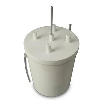
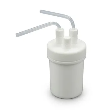
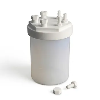
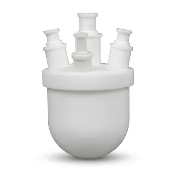
During radical copolymerization of fluorinated gaseous monomers, safety depends on controlling chemistry, heat release, and pressure as one integrated system. Use a pressure-rated, corrosion-resistant autoclave with a fluoropolymer-lined or otherwise chemically compatible reaction zone, verified leak-tight transfer hardware, effective oxygen removal, controlled heating and cooling, and independent overpressure protection. Monitor pressure continuously and interpret it together with temperature, agitation, and mass-balance data rather than treating any single pressure change as proof of conversion.
The central protocol is to establish a clean, oxygen-free, leak-tight system; suppress acid-catalyzed side reactions with an appropriate weak base; track the thermal expansion and subsequent monomer-consumption pressure profile; and maintain independent engineering safeguards against runaway reaction or blocked pressure relief.
Establishing a Safe Reaction Envelope
Confirm the apparatus rating
The autoclave, piping, valves, fittings, sensors, and transfer lines must be rated for the maximum credible pressure and temperature, including thermal expansion, reaction exothermicity, blocked outlets, and abnormal operating conditions.
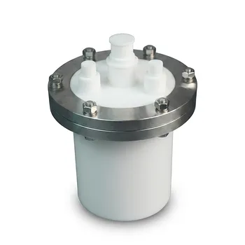
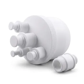
Use 316 or higher-grade stainless steel where metal surfaces contact the process, together with compatible PTFE or PFA components where fluorinated gases, solvents, or reactive intermediates require fluoropolymer contact surfaces.
Provide independent pressure relief
Install a properly sized rupture disc or equivalent pressure-relief device that discharges to a controlled, ventilated system suitable for the expected fluorinated materials.
Inspect the relief path and rupture disc before use. Fluoropolymer buildup can obstruct or delay venting, defeating the primary protection against vessel rupture.
Use physical containment and remote operation
Because fluorinated monomers can be flammable under air and may be handled at very high pressure, operate the equipment in appropriate ventilated, blast-resistant containment with intrinsically safe instrumentation and controls.
Pressure relief, high-temperature shutdown, loss of cooling, and abnormal-pressure alarms should be independent of ordinary process-control software where practical.
Preparing the Reactor Before Charging
Verify leak-tightness
Before introducing fluorinated monomers, perform an approved inert-gas pressure test. The cited procedure uses nitrogen pressurization to approximately 30 bar, but the test pressure and hold time must be defined by the equipment owner, applicable procedures, and vessel rating.
A pressure test is only meaningful if pressure decay is logged against temperature and isolated from unaccounted leakage paths. Do not proceed when fittings, valves, seals, or instrumentation show unexplained loss of pressure.
Remove oxygen systematically
Oxygen removal is essential because residual oxygen can inhibit radical polymerization and create a flammable mixture with fluorinated monomers.
A representative sequence is inert-gas purging followed by evacuation under high vacuum. The reference describes evacuation near 10^-2 mbar for about 40 minutes, but the acceptance criterion should be based on the validated reactor procedure and oxygen measurement where available.
Charge liquids and initiators under inert conditions
Introduce liquid reactants and dissolved initiators through closed, inert-compatible transfer paths. Use high-purity PTFE or PFA tubing, valves, and fittings when they provide the required chemical compatibility and sealing performance.
Add potassium carbonate or another validated weak base before heating when the formulation is susceptible to trace-acid effects. The base neutralizes acidity that could otherwise promote vinyl-ether homopolymerization or unwanted acetal formation.
Add gaseous monomers with controlled inventory
Charge CTFE, HFP, PMVE, or comparable gaseous monomers through a controlled, closed system. Differential weighing can be used to determine the amount transferred, provided the weighing system, cylinder, transfer line, and temperature corrections are included in the material balance.
Record initial mass, pressure, temperature, and composition information before heating. These values establish the baseline needed to interpret later pressure changes.
Monitoring Pressure and Temperature During Polymerization
Separate thermal expansion from monomer consumption
At the start of heating, pressure may rise because the gas expands and the liquid and vessel contents warm. This initial rise is not evidence of polymerization or overpressure by itself.
As radical copolymerization proceeds, monomer consumption commonly produces a substantial pressure decline. In the cited fluorinated copolymerizations, a decrease of approximately 9 to 12 bar may correspond to significant monomer uptake, but the expected value is formulation- and equipment-dependent.
Use synchronized pressure and temperature data
Log pressure and temperature continuously at a rate sufficient to resolve the expected reaction behavior. A pressure trace without its corresponding temperature trace is difficult to interpret because pressure changes can result from heating, cooling, gas dissolution, leakage, or chemical consumption.
The most useful profile typically shows:
- A controlled pressure increase during heat-up.
- A transition as the reaction accelerates.
- A sustained pressure decrease associated with monomer consumption.
- Stabilization as conversion slows or the monomer inventory is depleted.
Watch for abnormal pressure behavior
A rapid pressure increase beyond the expected thermal profile can indicate excessive reaction rate, inadequate cooling, decomposition, blocked relief, or an instrumentation problem.
A pressure decrease that is faster than expected can indicate accelerated monomer consumption or a leak. Do not assume that a falling pressure is safe; compare it with temperature, agitation, vessel isolation status, and independent inventory measurements.
Control heat removal
The reactor should have a functioning heating and cooling jacket capable of removing reaction heat promptly. Establish high-temperature alarms and automatic shutdown or cooling actions before charging monomers.
If temperature rises unexpectedly, stop further monomer addition, remove heat, activate the validated emergency response, and avoid opening or manually venting the reactor until the system has been declared safe.
Verifying Completion Without Relying on One Signal
Cool before depressurization or opening
After the reaction hold, cool the autoclave in a controlled manner. The reference identifies an ice bath before opening, but the actual cooling method must be compatible with the vessel, contents, seals, and thermal-shock limits.
Do not open a pressurized vessel. Confirm pressure is at the approved safe condition and route any remaining gas through a controlled treatment or vent system.
Treat degassing as supporting evidence
The absence of noticeable gas release during degassing can support the conclusion that gaseous monomers have been substantially consumed. It is not, by itself, definitive proof of quantitative conversion.
Confirm conversion using the available analytical and material-balance methods, such as residual-gas measurement, pressure and temperature history, initial-versus-final inventory, and polymer characterization.
Reconcile the pressure trace with the material balance
The final pressure should be interpreted against the starting monomer charge, reactor volume, temperature, solvent uptake, and any gas remaining in dead legs or transfer lines.
A pressure drop alone cannot distinguish complete conversion from leakage or other physical changes. Conversion claims should therefore require agreement among the pressure profile, degassing behavior, and independent analytical evidence.
Understanding the Trade-offs
Higher pressure improves inventory but raises consequence
Increasing monomer pressure can provide a larger reactant inventory and affect reaction rate and composition. It also increases stored energy, leakage consequences, relief requirements, and the severity of any uncontrolled depressurization.
The operating pressure should therefore be selected from validated kinetics and equipment limits, with sufficient margin below the relief-device set point.
Fluoropolymer components improve compatibility but need inspection
PTFE and PFA components can reduce contamination and resist aggressive fluorinated solvents and gases. However, seals, compression fittings, tubing, and valves can still creep, deform, permeate, or fail under pressure and temperature cycling.
Inspect these components before every campaign and replace them according to a documented service-life program rather than relying only on visual condition.
Pressure monitoring cannot replace engineering safeguards
A pressure sensor may fail, drift, plug, or report an incorrect value. A control system may also misinterpret pressure changes caused by temperature or leakage.
Use independent high-pressure and high-temperature alarms, calibrated sensors, a verified relief device, and physical containment. Relief hardware must remain available even when the control system or power supply fails.
Do not overinterpret cited operating values
Values such as 75 °C, 9-12 bar pressure decline, 30 bar nitrogen testing, and 10^-2 mbar evacuation are process examples, not universal settings.
They must be confirmed through reaction-specific hazard assessment, calorimetry or validated process data, equipment design calculations, current safety data sheets, and the site’s approved operating procedure.
Making the Right Choice for Your Goal
The safest implementation is a written operating envelope that defines normal trends, alarm limits, shutdown actions, and evidence required before opening the reactor.
- If your primary focus is reaction control: Use a validated pressure-temperature profile, pre-add a weak base where required, and correlate pressure decline with temperature, monomer inventory, and analytical conversion data.
- If your primary focus is pressure safety: Use a pressure-rated and leak-tested apparatus, independent alarms and interlocks, inspected rupture-disc protection, and blast-resistant containment with controlled venting.
- If your primary focus is product purity: Use oxygen-free charging, passivated and chemically compatible contact surfaces, fluoropolymer transfer components where appropriate, and documented contamination controls.
- If your primary focus is reliable conversion verification: Cool under controlled conditions, degas through an approved path, and require agreement between the pressure trace, residual-gas evidence, material balance, and polymer analysis.
A defensible fluoropolymer reaction protocol treats pressure as both a process signal and a hazard signal, supported by independent safeguards and objective conversion checks.
Summary Table:
| Phase | Protocol | Key Monitoring Points |
|---|---|---|
| Setup | Use pressure-rated autoclave, corrosion-resistant materials, independent relief device | Verify pressure rating, test relief path, inspect PTFE/PFA components |
| Preparation | Leak test with inert gas (e.g., N2 to 30 bar), evacuate to ~10^-2 mbar, charge liquids under inert conditions | Log pressure decay vs temperature, confirm no leaks, remove oxygen |
| Reaction | Heat with controlled heating/cooling, add weak base if needed, charge gaseous monomers | Monitor pressure and temperature continuously, distinguish thermal expansion from consumption |
| Monitoring | Watch for pressure decline (e.g., 9-12 bar) as monomer is consumed | Track synchronized pressure/temperature traces, set alarms for abnormal pressure |
| Completion | Cool before depressurization, degas through controlled vent, verify conversion | Confirm pressure safe, check residual gas, reconcile with mass balance |
| Overall | Treat pressure as both process and hazard signal, use independent safeguards | Ensure relief always available, inspect PTFE/PFA components regularly, do not rely solely on pressure |
Ensure your high-pressure fluoropolymer reactions run safely and efficiently. At KINTEK, we specialize in PTFE and PFA labware, custom reaction apparatus, and high-pressure fluoropolymer components designed for demanding applications. Our products help you maintain precise control over your reactions, from autoclaves to transfer lines. Contact our experts today to find the right solution for your process — get in touch.
Related Products
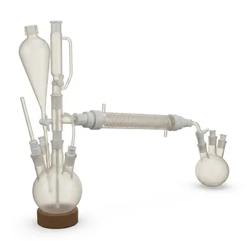
- PTFE Distillation Condensation Apparatus High Temperature Hydrofluoric Acid Resistant Fluorination Reaction Flask
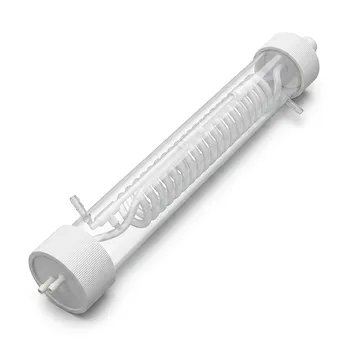
- High Purity PFA Condenser Serpentine Straight HF Resistant Reaction Apparatus Custom Circulation Column
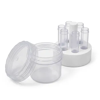
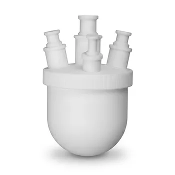
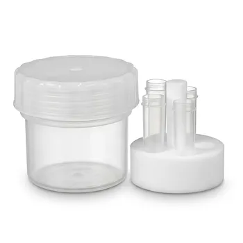
- High Purity Corrosion Resistant PFA Reaction Vessel with PTFE Holder and Integrated Sampling Tube for Trace Analysis
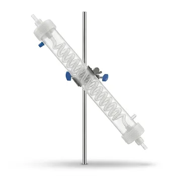
- Custom PFA Serpentine Straight Condenser HF Resistant Reaction Device Laboratory Cooling Column
- High Purity Custom PTFE Large Volume 15L Flask Corrosion Resistant Low Trace Background Fluoropolymer Reaction Vessel
People Also Ask
- How does the low surface energy of PTFE benefit the condensation process? Boost Heat Transfer and Prevent Fouling
- What structural characteristics provide PTFE fluoropolymer laboratory apparatus with high thermal stability? Strong C-F bonds, dense fluorine shielding, and rigid helical conformation ensure stability during high-temperature analysis.
- How can autopolymerization of TFE gas be prevented during storage and handling? Master TFE safety with oxygen control, inhibitors, and robust system design.
- When synthesizing fluorinated polymers using volatile and toxic monomers like octafluorocyclopentene (OFCP) or decafluorocyclohexene (DFCH), what material safety and thermal features are required for fluoropolymer laboratory reaction apparatus and fluid h
- How do pyrolysis temperature and steam diluent ratios influence tetrafluoroethylene (TFE) conversion and yield in fluoropolymer monomer reaction apparatus? Optimize TFE yield with temperature and steam control