β-phase fluoropolymer interfaces suppress lithium dendrites by regulating where and how Li⁺ is reduced. In ferroelectric β-phase PVDF, aligned molecular dipoles create a fluorine-rich, electronegative interface on the metal anode. This interfacial field helps distribute Li⁺ more uniformly, encouraging layer-by-layer lithium deposition instead of localized growth into hazardous dendrites.
The interface controls lithium deposition through both surface electronegativity and polarization direction. The testing apparatus should therefore use chemically compatible, thermally stable fluoropolymer components while preserving the ability to control electrode orientation, electrolyte exposure, current distribution, and pressure.
How the β Phase Changes the Anode Interface
Why β-phase PVDF is functionally different
PVDF can exist in several crystalline phases, but its β phase is strongly ferroelectric because its molecular dipoles are aligned. At a lithium or copper surface, this produces an electronegative, fluorine-rich interface.
That interface is not merely a passive coating. Its electrostatic character affects the movement of Li⁺ through the electrode-electrolyte boundary, where small variations in ion flux can determine whether deposition remains uniform.
How the interface suppresses dendrites
Dendrites typically develop when lithium deposition becomes concentrated at local protrusions or regions of high current density. Once a protrusion forms, it can attract further deposition and accelerate uneven growth.
A β-phase fluoropolymer interface promotes a more even Li⁺ distribution across the metal surface. More uniform interfacial transport supports flatter, layer-by-layer deposition and reduces the conditions that allow dendrites to amplify.
Why polarization alignment matters
The benefit depends partly on the orientation of the fluoropolymer’s polarization axis. Aligning that axis with the intended Li-ion transport direction can enhance ion movement across the electrode-electrolyte interface.
This means that a meaningful experiment must document more than the polymer’s chemical identity. It should also control or record the phase, polarization state, coating orientation, thickness, and contact geometry.
What This Means for Electrochemical Testing Apparatus
Separate the active interface from the cell hardware
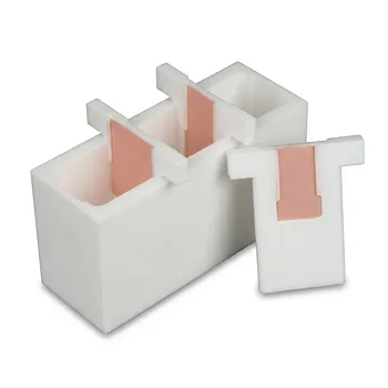
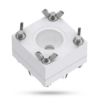
The β-phase PVDF layer is the electrochemically functional interface. The fluoropolymer cell body, spacers, holders, and seals serve a different purpose: they provide a stable environment in which the interface can be tested.
Confusing these roles can lead to poor experimental design. A fluoropolymer cell component does not automatically create the same dendrite-suppressing effect as a polarized β-phase PVDF coating on the electrode.
Select materials for chemical compatibility
Lithium metal and organic electrolytes are highly reactive toward unsuitable construction materials. Wetted components should therefore be made from fluoropolymers selected for compatibility with the specific electrolyte, lithium species, cleaning process, and operating temperature.
Fluoropolymer construction reduces the risk that the cell body or fittings will introduce reactive contaminants, absorb electrolyte, or degrade during cycling. The claim should be treated as application-specific rather than as universal chemical inertness for every fluoropolymer and solvent combination.
Require thermal and dimensional stability
Dendrite and interphase studies often involve extended cycling, controlled-temperature testing, or localized heating. The apparatus must retain its shape, sealing force, and electrode alignment over the full test temperature range.
Thermal stability is especially important because dimensional changes can alter stack pressure, separator contact, electrode spacing, and current distribution. Those changes can be mistaken for effects caused by the β-phase interface.
Preserve controlled electrode geometry
A suitable cell should hold the working electrode, counter electrode, separator, and current collectors in a reproducible arrangement. Uniform spacing and stable pressure are essential because mechanical contact and current density directly influence lithium morphology.
The cell should also allow researchers to position the PVDF polarization axis consistently relative to the electrode and electrolyte. Without that control, comparisons between samples may mix material effects with orientation effects.
How to Design the Test Around the Mechanism
Measure deposition morphology directly
Dendrite suppression should be evaluated through lithium morphology, not inferred solely from cell voltage. Microscopy, post-cycling surface analysis, and cross-sectional examination can reveal whether deposition is compact and layered or porous and filamentary.
The apparatus should make electrode recovery practical while minimizing air and moisture exposure after testing. A design that supports controlled disassembly improves the reliability of interphase and morphology measurements.
Control electrochemical variables
The cell should support stable control of current density, areal capacity, cycle duration, electrolyte volume, separator condition, and temperature. These variables strongly affect whether dendrites form, even when the interface material is unchanged.
A useful apparatus also permits symmetric-cell and asymmetric-cell configurations. Lithium-lithium cells can isolate plating and stripping behavior, while lithium-copper cells can help evaluate initial deposition and interfacial nucleation.
Use appropriate control samples
A β-phase PVDF experiment requires controls that distinguish phase and polarization effects from ordinary polymer effects. Relevant comparisons may include an uncoated electrode, a nonpolarized PVDF interface, or a different PVDF phase under otherwise matched conditions.
The apparatus must keep the electrode area, current path, pressure, electrolyte exposure, and temperature consistent across those comparisons. Otherwise, an apparent improvement may originate from cell geometry rather than interfacial polarization.
Avoid introducing measurement artifacts
Fluoropolymer components should not obstruct electrical contact or create unintended insulating layers between the electrode and current collector. Seals and spacers must be positioned so that they do not change the active area from one test to another.
The apparatus should also minimize dead volume and leakage. Changes in electrolyte quantity or composition can alter interphase formation and lithium transport, undermining comparisons between experiments.
Understanding the Trade-offs
Chemical resistance is not absolute
Fluoropolymers are generally attractive for reactive electrochemical environments, but compatibility depends on the exact polymer grade, electrolyte solvent, additives, temperature, pressure, and exposure time. A material that performs well with one organic electrolyte may not be suitable for another formulation or elevated-temperature condition.
Material selection should therefore be verified against supplier compatibility data and, where necessary, preconditioned through solvent-exposure tests.
Mechanical compliance can affect results
Some fluoropolymer components are relatively compliant compared with metals or ceramics. Under clamping pressure, they may deform and change electrode spacing or contact pressure.
That compliance can be useful for sealing, but uncontrolled deformation introduces a mechanical variable into a dendrite experiment. The cell should use defined compression limits and a reproducible clamping procedure.
Polarization may change during operation
The electrostatic behavior of a PVDF interface can depend on how it was processed and polarized. Thermal history, mechanical stress, cycling, electrolyte exposure, and surface condition may alter the effective interfacial response.
The polarization state should be characterized before testing and considered when interpreting long-term cycling data. A nominally identical coating may not provide identical behavior if its processing history differs.
Dendrite suppression is not a complete battery solution
A β-phase fluoropolymer interface can improve Li⁺ transport uniformity and reduce hazardous deposition, but it does not eliminate all failure mechanisms. Electrolyte instability, separator defects, poor stripping efficiency, dead lithium, mechanical fracture, and excessive current density can still cause degradation.
The apparatus should support evaluation of both plating and stripping, because stable deposition alone does not establish durable full-cell performance.
Making the Right Choice for Your Goal
Choose the apparatus according to the scientific variable you need to isolate.
- If your primary focus is dendrite morphology: Use a cell with stable electrode alignment, controlled pressure, optical or post-test access, and precisely defined active area.
- If your primary focus is polarization-assisted Li⁺ transport: Use a design that fixes and documents the β-phase PVDF polarization axis relative to the electrode-electrolyte interface.
- If your primary focus is interphase chemistry: Select low-contamination fluoropolymer wetted parts and enable controlled disassembly for surface and cross-sectional analysis.
- If your primary focus is long-term cycling: Prioritize electrolyte compatibility, thermal stability, reliable sealing, and dimensional stability over convenience of assembly.
- If your primary focus is material comparison: Use identical cell geometry and operating conditions for coated, uncoated, polarized, and nonpolarized control samples.
A well-designed fluoropolymer electrochemical apparatus does not create the dendrite-suppressing mechanism itself; it preserves and measures that mechanism without adding chemical, thermal, mechanical, or geometric artifacts.
Summary Table:
| Factor | Role in Dendrite Suppression | Testing Apparatus Requirement |
|---|---|---|
| Surface Electronegativity | Distributes Li+ uniformly | Use materials with compatible surface properties |
| Polarization Direction | Enhances Li+ transport | Fix and document polarization axis |
| Chemical Compatibility | Prevents side reactions | Select fluoropolymers compatible with electrolyte |
| Thermal Stability | Maintains cell integrity | Ensure dimensional stability over temperature range |
| Electrode Geometry | Ensures uniform current | Reproducible electrode spacing and pressure |
| Control Samples | Distinguishes phase effects | Use uncoated, nonpolarized, or different phase controls |
Ready to achieve precise dendrite suppression in your research? KINTEK offers high-performance PTFE and PFA electrochemical cells designed to preserve β-phase fluoropolymer interfaces. Our custom CNC machining ensures exact polarization orientation and geometry. From standard cells to bespoke setups, we support your experiments. Contact us today to discuss your requirements!
Related Products
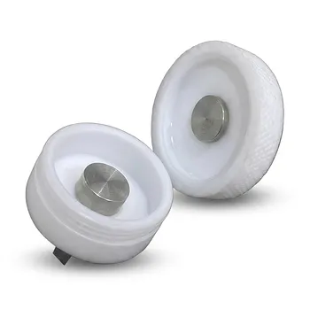
- Corrosion Resistant PTFE Coin Cell Battery Testing Clamps and Acid Proof Custom Fluoropolymer Battery Fixtures
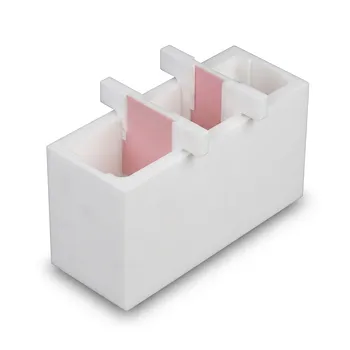
- Corrosion Resistant PTFE Electrochemical Cell for New Energy Research Inert Insulating Customizable Lab Reaction Vessel
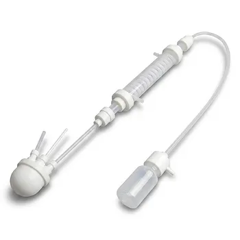
- Corrosion Resistant Hydrogen Fluoride Reflux Apparatus PTFE Flask Condenser Separatory Funnel Collection Bottle High Temperature Laboratory System
- Customizable PFA Square Tray Corrosion Resistant High Temperature Large Petri Dish Electrolytic Cell
- Custom PTFE Test Tubes Corrosion Resistant Low Background Fluoropolymer Labware 50ml 30ml
People Also Ask
- What is the thermal operating range for PTFE battery clamps in electrochemical research? Stability from -200°C to +260°C
- What are the primary functions and material compositions of PTFE battery clamps? Ensure Precision & Chemical Resistance
- How do coin cell testing fixtures evaluate ZIF-derived LCO cycling stability? Ensure Battery Research Precision
- What are the electrical insulation and signal integrity advantages of using PTFE battery clamps? Ensure Data Accuracy
- How does the chemical inertness of PTFE benefit laboratory-scale battery testing? Ensure high-purity research results.