For precision analytical instrument components, PTFE, PFA, and FEP all provide excellent electrical insulation, but their moisture-barrier performance is not identical. Their dielectric constants are approximately 2.1, with very low dissipation factors and high dielectric strength, making all three suitable for sensitive electrochemical, high-frequency, and signal-transmitting applications. For water vapor permeability, the cited comparative data place PFA and FEP ahead of PTFE, although the final choice also depends on component geometry, processing method, temperature, and the required purity level.
PTFE, PFA, and FEP are all electrically excellent fluoropolymers. Choose among them primarily by balancing moisture resistance, fabrication requirements, mechanical function, and analytical purity rather than by dielectric performance alone.
How Their Dielectric Properties Compare
Dielectric Constant
PTFE, PFA, and FEP have similarly low dielectric constants, generally around 2.1 under commonly reported conditions. This low permittivity reduces capacitive loading and helps preserve the behavior of high-impedance sensors, electrochemical cells, and miniature signal paths.
The reference’s values below 0.0002 to 0.0003 are more appropriately interpreted as dissipation factor values, not dielectric constants. A dielectric constant below 1 would not be physically appropriate for these solid fluoropolymers.
Dissipation Factor
All three materials have exceptionally low dielectric losses. Reported dissipation factors are approximately 0.0002 to 0.0004 at low test frequencies, with PTFE remaining below approximately 0.0004 across frequencies extending toward 100 MHz.
Low dissipation factor matters when the component is exposed to alternating electric fields. It limits dielectric heating and signal loss, supporting stable measurements in sensitive analytical instrumentation.
Dielectric Strength
The materials also provide high dielectric strength, with the supplied comparison giving a range of approximately 4,000 to 6,500 V/mil. PTFE is reported at approximately 24 kV/mm for a specified 2.03 mm thickness.
Actual breakdown performance depends on thickness, voids, surface condition, temperature, humidity, and manufacturing quality. For precision components, the material’s nominal rating should therefore be verified against the specific geometry and test standard.
Temperature and Frequency Stability
PTFE’s dielectric properties remain relatively stable across a broad temperature range, reported from approximately -40°C to 240°C, and across a wide frequency spectrum. PFA and FEP similarly provide stable insulation performance for demanding laboratory environments.
This stability is valuable in components such as sensor probes, insulated electrodes, feedthroughs, custom electrochemical cells, and fluidic parts that transmit electrical signals while containing reactive chemicals.
How Water Vapor Permeability Compares
Comparative Permeability Data
The supplementary reference reports water vapor permeability of approximately:
- PFA: 13 × 10⁻¹³ cm³·cm/(cm²·s·Pa)
- FEP: 13 × 10⁻¹³ cm³·cm/(cm²·s·Pa)
- PTFE: 25 × 10⁻¹³ cm³·cm/(cm²·s·Pa)
On these values, PFA and FEP offer lower water vapor permeation than PTFE. In other words, they provide the stronger nominal barrier against moisture diffusion under the cited test conditions.
This conflicts with the primary reference’s broader statement that FEP and PTFE outperform PFA. Because the quantitative values provide a clearer basis for comparison, the more defensible conclusion is that PFA and FEP are approximately comparable and somewhat better than PTFE for water vapor resistance, subject to grade and test-condition differences.
Why Moisture Permeability Matters
Water vapor can diffuse through a polymer by moving through free volume or by being absorbed, transported, and released within the material. Even when the rate is low, long exposure times, thin walls, elevated temperatures, and large surface areas can make moisture ingress significant.
Lower permeability helps protect moisture-sensitive reagents, maintain controlled fluid composition, reduce corrosive vapor migration, and limit contamination in high-purity fluid-handling systems.
Component Design Has a Major Effect
Permeability is a material property, but the practical moisture barrier is determined by the entire component. A thick PFA vessel, for example, may provide substantially better resistance to moisture transport than a thin FEP tube despite similar intrinsic material rates.
Joints, fittings, seals, welds, machining marks, and assembly gaps can also become the dominant leakage paths. Material selection should therefore be combined with a review of wall thickness, diffusion distance, connection design, and exposure time.
Material-Specific Strengths
PTFE: Electrical Insulation and Low Friction
PTFE offers the lowest coefficient of friction among the three materials and is well suited to sliding seals, stopcocks, stir-bar coatings, and other components where non-stick behavior is important. It also provides excellent chemical resistance and strong dielectric insulation.
PTFE is non-melt-processible and is commonly compression molded, sintered, or CNC machined. That makes it particularly useful for heavy-walled structural parts, custom electrochemical cells, crucibles, and precision-machined laboratory components.
PFA: Purity and Molded Fluidic Components
PFA combines excellent dielectric behavior and chemical resistance with melt processibility. It can be molded into seamless, translucent, or transparent components such as high-purity vessels, fittings, valve bodies, and sample containers.
This processing advantage can reduce joints and crevices where contamination or moisture ingress might occur. PFA is especially attractive when trace-metal control, visual inspection, and complex molded geometry are more important than the lowest possible friction.
FEP: Flexible Tubing and Electrical Isolation
FEP provides very low dielectric loss, high chemical resistance, and useful flexibility. Its lower melting range, approximately 260°C to 270°C, makes it suitable for tubing and flexible fluid-transfer components where PTFE’s processing characteristics or stiffness are less convenient.
The cited water vapor data place FEP alongside PFA as the lowest-permeability option of the three. FEP is therefore a strong candidate for thin-wall fluidic lines when both electrical isolation and moisture resistance are required.
Understanding the Trade-offs
Do Not Choose on Dielectric Constant Alone
The dielectric differences among PTFE, PFA, and FEP are usually small relative to the effect of component design, cable routing, shielding, electrode geometry, and measurement electronics. Selecting a polymer solely because it has a marginally lower reported dielectric value may not improve the instrument’s actual signal integrity.
The more consequential distinctions are often processing method, friction, flexibility, dimensional stability, purity, and moisture exposure.
Water Vapor Data Are Test-Dependent
Permeability values vary with temperature, humidity, specimen thickness, crystallinity, orientation, and test method. Published numbers should be treated as comparative guidance rather than universal guarantees for every commercial grade.
For a moisture-critical design, request data for the exact grade and verify the finished component under representative conditions.
Perfluoropolymers Are Not Maximum Gas Barriers
Although PFA, FEP, and PTFE provide strong resistance to water vapor and many chemicals, they are not impermeable barriers. The supplementary comparison indicates that PVDF can provide substantially lower oxygen and nitrogen permeability than these perfluoropolymers.
If the instrument must tightly control oxygen, nitrogen, or other gas concentrations, a fluoropolymer may need to be combined with a dedicated barrier layer or replaced with a lower-permeability material where chemical compatibility permits.
Processing Can Affect Analytical Performance
PTFE machining enables custom geometries but can introduce surface features, dimensional tolerances, and particulate concerns that must be controlled. PFA molding supports high-purity, seamless parts, while FEP is advantageous where flexibility and thin-wall fabrication are required.
The cleanest material on paper is not automatically the cleanest finished component. Manufacturing, cleaning, packaging, and assembly practices remain part of the analytical materials specification.
Making the Right Choice for Your Goal
The most reliable selection begins with the dominant failure mode: electrical interference, moisture diffusion, friction, contamination, or fabrication complexity.
- If your primary focus is electrical insulation and signal integrity: Any of the three is suitable, with dielectric constants near 2.1, very low dissipation factors, and high dielectric strength.
- If your primary focus is minimizing water vapor diffusion: Prefer PFA or FEP based on the cited permeability values, while validating the exact grade, thickness, and component design.
- If your primary focus is low friction and non-stick performance: Choose PTFE for sliding seals, stopcocks, stir bars, and other moving or release-critical components.
- If your primary focus is high-purity molded fluid handling: Choose PFA for seamless, translucent or transparent vessels, fittings, valves, and trace-analysis components.
- If your primary focus is flexible fluid transfer: Choose FEP when tubing flexibility, chemical resistance, electrical isolation, and low moisture permeation must be combined.
The best material is the one whose moisture, electrical, processing, and contamination characteristics match the complete analytical component rather than an isolated datasheet value.
Summary Table:
| Property | PTFE | PFA | FEP |
|---|---|---|---|
| Dielectric Constant | ~2.1 | ~2.1 | ~2.1 |
| Dissipation Factor | <0.0004 | 0.0002-0.0003 | 0.0002-0.0003 |
| Dielectric Strength | ~24 kV/mm | ~4,000-6,500 V/mil | ~4,000-6,500 V/mil |
| Water Vapor Permeability (cm³·cm/(cm²·s·Pa)) | 25 × 10⁻¹³ | 13 × 10⁻¹³ | 13 × 10⁻¹³ |
| Friction | Lowest | Moderate | Moderate |
| Processability | Non-melt, machined | Melt-processible | Melt-processible |
| Flexibility | Low | Moderate | High |
Optimize your analytical instruments with precision PTFE/PFA/FEP components. At KINTEK, we specialize in fabricating high-performance fluoropolymer parts for critical applications. With extensive expertise in CNC machining and custom fabrication, we can produce components that meet your exact specifications for dielectric stability and moisture control. Contact our engineers today to discuss your requirements and discover how we can enhance your instrument's reliability — request a consultation.
Related Products
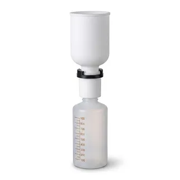
- PTFE PFA Vacuum Filtration System Corrosion Resistant Customizable Shatterproof Laboratory Device
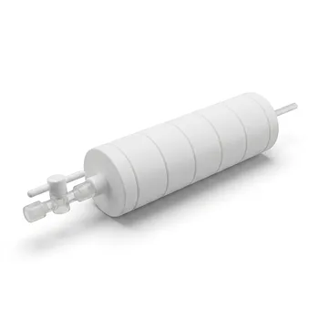
- PTFE Corrosion Resistant Filter with PFA Valve Connections and Integrated Sieve Plate
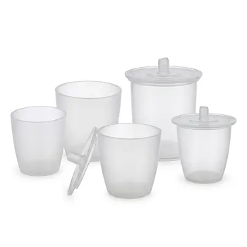
- High Purity PFA Crucible and Corrosion Resistant PTFE Beaker for Trace Analysis and Custom Laboratory Applications
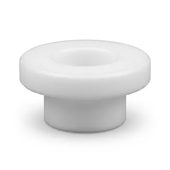
- Custom PTFE Insulating Gaskets and Corrosion Resistant Fluoropolymer Seals for Industrial Electrical Applications
- Corrosion Resistant PFA Reaction Tank High Purity Laboratory Reaction Bottle Wide Mouth PTFE Jar Multiple Specifications
People Also Ask
- What makes PTFE filtration systems advantageous for industrial and scientific use? Unmatched Chemical & Thermal Stability
- How does the hydrophobicity of PTFE filters benefit their use? Ensure Uninterrupted Gas Flow and Solvent Filtration
- What temperature resistance do PTFE filters offer? Unmatched Thermal Stability from -200°C to +260°C
- Which chemicals are fully compatible with PTFE filters? Discover Unmatched Chemical Resistance
- What sizes and pore options are available for PTFE filters? Choose the Right Filter for Your Application