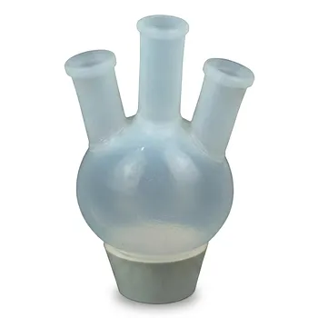
Melt-processable FEP is easier to manufacture into complex custom components, while virgin PTFE provides superior temperature capability and mechanical endurance. FEP’s lower crystallinity reduces its melt viscosity to approximately 10^4–10^5 poise, compared with roughly 10^10–10^12 poise for PTFE, enabling injection molding, extrusion, and other conventional thermoplastic processes. The trade-off is that FEP melts and thermally degrades at lower temperatures and generally offers lower tensile strength and mechanical endurance than PTFE.
FEP is the better choice when component geometry, transparency, heat sealing, or conventional melt processing matters most. Virgin PTFE remains preferable for the highest service temperatures, extreme chemical exposure, low friction, and demanding mechanical applications, provided that specialized fabrication is acceptable.
Why FEP Can Be Melt-Processed
Lower crystallinity changes processing behavior
Virgin PTFE has approximately 92–98% crystallinity, while virgin FEP typically has 40–50% crystallinity. FEP’s hexafluoropropylene-derived trifluoromethyl side groups disrupt the regular packing of the PTFE backbone.
This structural change reduces the resistance of the polymer chains to flow when heated. FEP therefore behaves as a conventional thermoplastic during processing, whereas PTFE does not form a practical processing melt.
FEP supports conventional manufacturing
FEP can be processed using methods such as:
- Injection molding
- Melt extrusion
- Blow molding
- Heat sealing
- Film and tubing production
These methods are well suited to complex molded parts, transparent or translucent tubing, sealed bags, protective films, fittings, and intricate fluid-handling components.
PTFE requires specialized fabrication
PTFE’s melt viscosity remains extraordinarily high, approximately 10^10–10^12 poise in the cited references. Conventional injection molding and extrusion are therefore impractical for virgin PTFE.
Custom PTFE components are usually produced by compression molding, sintering, fine-powder paste extrusion, or machining from molded stock shapes. This can provide excellent parts, but it adds tooling, processing, and design constraints.
Mechanical Property Comparison
PTFE generally provides greater mechanical endurance
Virgin PTFE is generally selected when the part must withstand demanding mechanical service, elevated temperatures, or extreme chemical exposure. It also offers high elongation, with reported break elongation in the range of 300–500%, and an exceptionally low static coefficient of friction of approximately 0.1.
These properties make PTFE useful for low-friction seals, high-temperature vessels, chemically resistant labware, and components exposed to sliding or rubbing contact.
FEP favors flexibility and manufacturability
FEP retains the characteristic chemical inertness and low-friction surface associated with fluoropolymers, but it generally has lower tensile strength and lower mechanical endurance than PTFE. Its lower crystallinity contributes to a more flexible material profile.
That combination is useful for fluid-transfer tubing, flexible liners, heat-sealable films, and molded parts whose geometry is more important than maximum mechanical loading capacity.
Geometry can matter more than nominal strength
For custom components, the relevant question is not simply which resin has the higher tensile strength. A PTFE part may have better high-temperature mechanical retention, but producing it may require machining, thicker walls, or a less intricate geometry.
FEP can often be molded as a near-net-shape component, reducing joints and machining operations. A correctly designed FEP part may therefore outperform a mechanically superior PTFE design when seamless construction, thin sections, transparency, or complicated flow paths are important.
Thermal Property Comparison
PTFE has the higher melting point
Virgin PTFE has a melting point near 327°C, with reference ranges of approximately 320–340°C. FEP melts at approximately 265°C, or roughly 260–270°C depending on grade.
PTFE therefore provides greater thermal margin during both operation and fabrication.
PTFE supports higher continuous service temperatures
The cited upper continuous-use temperatures are approximately:
- PTFE: 260°C
- FEP: 200°C
This difference is critical for components exposed continuously to high heat, such as reaction vessels, digestion equipment, furnace-adjacent hardware, and high-temperature seals.
FEP can still serve demanding laboratory and industrial applications, but its operating temperature must remain within the lower limit appropriate to the specific grade and loading condition.
FEP has lower thermal-degradation resistance
The TGA threshold for 1% per hour weight loss is approximately:
- PTFE: 465°C
- FEP: 380°C
The lower FEP value is associated with the tertiary carbon atoms at the copolymer branch points, which make FEP somewhat more susceptible to oxidation and thermal degradation than the highly regular PTFE structure.
This does not eliminate FEP from high-temperature use. It means that designers must account for both the continuous service temperature and the short-term exposure conditions during processing, heat sealing, welding, or thermal cycling.
Processing Implications for Custom Components
FEP reduces tooling and fabrication complexity
FEP’s melt processability allows complex shapes to be produced directly from a mold or die. This is valuable for parts containing:
- Internal channels
- Thin walls
- Integrated sealing features
- Complex fittings
- Transparent inspection areas
- Repeated production geometries
Molding can also reduce the number of assembled joints, which is important in high-purity fluid systems where crevices and contamination sources must be minimized.
PTFE remains well suited to machined custom parts
PTFE is often the more practical choice when the component is a one-off, low-volume, or highly customized part that can be machined from a molded billet. CNC machining supports rapid design changes and can produce specialized vessels, seals, electrochemical cells, and heavy-duty laboratory parts without injection-molding tooling.
The limitation is that machining cannot always reproduce the thin, seamless, or internally complex geometries achievable through FEP molding.
FEP can add optical and sealing functionality
FEP is valued for optical translucency and heat sealing, including applications requiring visual inspection of fluid flow or sealed flexible assemblies. These properties can be decisive for tubing, bags, films, and protective layers.
Virgin PTFE is generally selected for its low friction, thermal stability, and mechanical service performance rather than for melt-formed transparent structures.
Understanding the Trade-offs
FEP is not a direct thermal replacement for PTFE
FEP preserves much of PTFE’s chemical resistance, but it does not preserve PTFE’s full temperature range. Substituting FEP for PTFE in a component exposed near 260°C can lead to loss of mechanical performance or accelerated degradation.
The material choice must be based on the actual continuous temperature, transient peaks, pressure, and mechanical load.
Processing advantages do not eliminate design limitations
FEP is easier to mold, but it still requires appropriate control of melt temperature, residence time, cooling, shrinkage, and part geometry. Overheating or prolonged thermal exposure can damage the polymer.
Molded FEP parts should also be evaluated for dimensional stability, creep, wall thickness, weld-line behavior, and performance under pressure.
PTFE may be more expensive to fabricate but better in service
PTFE processing is more specialized, and machining complex parts can increase cost and production time. However, the added fabrication burden may be justified when the component requires maximum heat resistance, very low friction, or stronger mechanical retention at elevated temperature.
Selecting FEP solely because it is easier to process can create a service-life problem if the operating environment is closer to PTFE’s performance envelope.
Filled grades change the comparison
The comparison above concerns virgin FEP and virgin PTFE. Fillers such as glass, carbon, bronze, or mineral additives can significantly change stiffness, wear resistance, creep, thermal expansion, and electrical behavior.
A filled PTFE or FEP grade should therefore be evaluated separately from the unfilled resins, particularly when the custom part carries load or must maintain tight tolerances.
Making the Right Choice for Your Goal
FEP and virgin PTFE are both chemically resistant fluoropolymers, but they solve different manufacturing and performance problems.
- If your primary focus is complex molded geometry: Choose FEP when injection molding, extrusion, integrated channels, thin walls, or reduced assembly are central requirements.
- If your primary focus is maximum temperature resistance: Choose virgin PTFE because its approximately 260°C continuous-use limit and higher melting point provide greater thermal margin.
- If your primary focus is flexible transparent tubing or heat-sealed assemblies: Choose FEP for its flexibility, optical translucency, and sealing capability.
- If your primary focus is low friction and mechanical endurance: Choose virgin PTFE, especially for sliding seals and demanding high-temperature mechanical service.
- If your primary focus is low-volume custom fabrication: Choose PTFE when the part can be machined from stock and the service environment justifies its superior thermal and mechanical performance.
- If your primary focus is high-volume repeatable production: Choose FEP when the component can be designed around conventional molding or extrusion and its lower temperature limit is acceptable.
The right selection balances service temperature, mechanical loading, geometry, production volume, and fabrication method, rather than treating melt processability as an overall measure of material superiority.
Summary Table:
| Property | FEP | PTFE |
|---|---|---|
| Crystallinity | 40-50% | 92-98% |
| Melt Viscosity | 10^4-10^5 poise | 10^10-10^12 poise |
| Melting Point | ~265°C | ~327°C |
| Continuous Service Temp | ~200°C | ~260°C |
| TGA Limit (1%/hr) | ~380°C | ~465°C |
| Tensile Strength | Lower | Higher |
| Elongation at Break | Not specified | 300-500% |
| Static Coefficient of Friction | Low | ~0.1 |
| Processability | Injection molding, extrusion | Compression molding, sintering, machining |
| Key Advantages | Complex geometries, transparency, heat sealing | Superior thermal, mechanical, and chemical resistance |
Need help choosing between FEP and PTFE for your custom components? At KINTEK, we specialize in high-performance fluoropolymers, offering both materials with fully customizable CNC machining capabilities. Whether you need precision-machined PTFE parts for extreme conditions or complex FEP molded components for fluid handling, our experts are ready to assist you. Contact us today to discuss your project and get a tailored solution that maximizes performance and durability. Contact KINTEK
Related Products
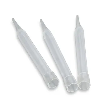
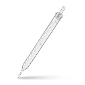
- Reusable FEP Pipette Tips Corrosion Resistant Fluoropolymer Labware Compatible with 5ml Pipettors
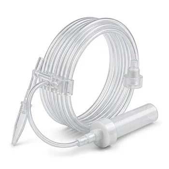
- High Purity PFA Coiled Tubing Custom PTFE Machining PFA Welding and Precision Bending Solutions
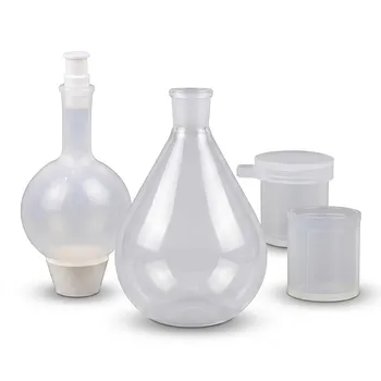
- PFA Eggplant Flask Custom Molded Pear Shaped Laboratory Flask Corrosion Resistant Glass Alternative
- Custom PFA Tubing 1/4 Inch High Purity Corrosion Resistant Fluoropolymer Tube with Welding and Machining Services
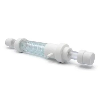
- Custom PTFE Condenser Tube 100ml Serpentine and Straight Fluoropolymer Laboratory Heat Exchanger with Flask Adapters
People Also Ask
- How do FEP and PTFE compare regarding continuous operating temperature and thermal stability for chemical handling components? Discover which polymer offers superior heat resistance for your lab.
- What is FEP and how does it differ from PTFE? Key Differences in Performance & Manufacturing
- What shear rate ranges are typical for fluid handling processes like pumping, mixing, and spraying? Understand the impact on PTFE/PFA component selection.
- What material handling and process control precautions are required when synthesizing moisture-sensitive fluoropolymer intermediates? Essential Guidelines for Safe and Efficient Synthesis