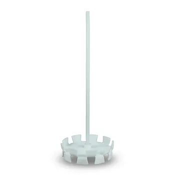
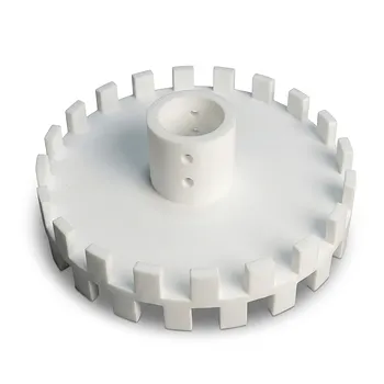
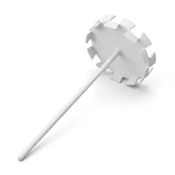
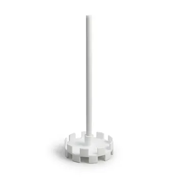
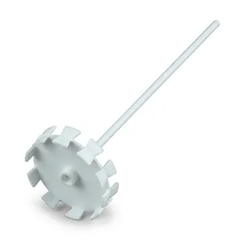
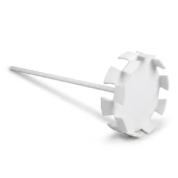
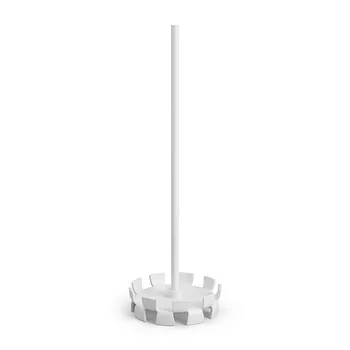
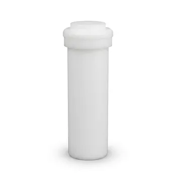
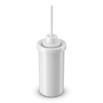
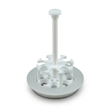
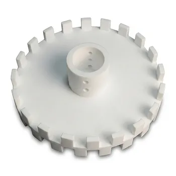
For fluoropolymer slurry preparation, configure the high-speed disperser around the vessel-to-blade ratio, bottom clearance, and target tip speed. For millbases in the 1,000–25,000 cP range, the sawtooth disperser blade should be approximately one-third of the vessel diameter, with the blade positioned at least 0.5 blade diameters above the flat vessel floor. The target operating tip speed is approximately 5,000 ft/min, while the vessel and wetted components should resist the selected solvent system and minimize product adhesion.
Core takeaway: Use a flat-bottom vessel with a sawtooth blade diameter near one-third of the vessel diameter, maintain a minimum bottom clearance of half the blade diameter, and operate near 5,000 ft/min tip speed. For chemically aggressive fluoropolymer formulations, custom PTFE or PFA vessel and liner construction may be necessary.
Configure the Vessel and Blade Geometry
Match blade diameter to vessel diameter
The sawtooth disperser blade diameter should be approximately:
[ D_\text{blade} \approx \frac{1}{3}D_\text{vessel} ]
This ratio provides the disperser with sufficient working reach while preserving vessel volume for circulation around the blade.
A blade that is too small may produce weak bulk circulation and poor turnover. An excessively large blade can increase torque, loading, and the risk of wall interaction.
Maintain the required bottom clearance
In a flat-bottom vessel, position the blade at least:
[ C_\text{bottom} \geq 0.5D_\text{blade} ]
above the vessel floor.
This clearance helps the slurry circulate beneath the blade instead of creating an overly restricted high-shear zone at the bottom. It also reduces the likelihood of scraping, localized heating, or accumulation of undispersed material.
Use a flat-bottom vessel where this ratio applies
The stated clearance guideline is specifically based on a flat-bottom container. Vessel geometry should therefore be evaluated as a complete system rather than treating the blade diameter as an isolated specification.
The bottom shape, liner thickness, shaft position, and usable liquid level can all affect the actual flow pattern.
Set the Operating Parameters
Target approximately 5,000 ft/min tip speed
The recommended operating target is approximately:
[ V_\text{tip} \approx 5{,}000\ \text{ft/min} ]
Tip speed is determined by blade diameter and rotational speed:
[ V_\text{tip}=\frac{\pi D_\text{blade}N}{12} ]
where (D_\text{blade}) is in feet and (N) is rotational speed in revolutions per minute.
Accordingly, the required rpm must be calculated from the selected blade diameter rather than specified independently.
Account for the 1,000–25,000 cP viscosity range
The geometry and speed guidance applies to millbases operating between 1,000 and 25,000 cP. This is a substantial viscosity range, so the drive system must be capable of handling the corresponding torque demand at the selected speed.
A formulation near the upper end of the range may require more conservative startup and speed-ramping procedures, even if the final target tip speed remains approximately 5,000 ft/min.
Confirm the vessel can tolerate the process load
The mixer configuration should be checked for mechanical loading, shaft stability, and compatibility with the intended batch volume. The blade must remain properly immersed, but the operating liquid level should also leave adequate headspace for circulation and process control.
The exact fill level is not defined by the stated geometry guideline and should be established through equipment design and process trials.
Select Materials for Fluoropolymer Slurries
Use fluoropolymer-compatible wetted surfaces
Strong solvent systems and fluoropolymer slurries can create two separate problems: chemical attack on wetted components and product adhesion to the vessel or liner.
Custom CNC-machined PTFE and PFA vessels, liners, and laboratory-scale mixing assemblies are used when standard materials cannot reliably meet the required chemical resistance or dimensional tolerances.
Preserve the dimensional ratios through the liner
A liner is not dimensionally neutral. Its thickness can reduce the effective vessel diameter and alter the blade-to-vessel ratio and bottom clearance.
The geometry should therefore be calculated using the actual wetted internal dimensions after liner installation, not merely the nominal outer vessel dimensions.
Consider adhesion and cleanability
The material choice should address both compatibility and cleanability. A chemically resistant surface that allows significant fluoropolymer buildup may still create batch-to-batch contamination, altered viscosity, or reduced effective vessel volume.
Keep HSD Slurry Preparation Separate from High-Pressure Synthesis Design
Do not confuse an HSD vessel with a reaction vessel
The geometry and operating parameters above apply to high-speed disperser slurry preparation. They do not, by themselves, define the requirements for a high-pressure fluoropolymer synthesis reactor.
High-pressure synthesis equipment may require grade 316 or higher stainless steel, passivated internal surfaces, heating and cooling capability, and dedicated overpressure protection.
Apply pressure-safety requirements only where relevant
If the same process includes a pressurized reaction stage, that equipment should include a properly specified safety rupture disc and inspection program. Fluoropolymer buildup on the disc can obstruct pressure relief and create a serious explosion hazard.
These pressure-vessel provisions should not be assumed to replace the HSD’s mixing-geometry requirements, nor should an HSD slurry vessel be treated as a pressure reactor without a separate engineering assessment.
Understanding the Trade-offs
Higher speed does not automatically mean better dispersion
The approximate 5,000 ft/min target provides a useful operating basis, but excessive speed can increase heat generation, solvent evaporation, torque demand, and component wear.
The final operating speed should be verified against the formulation, batch size, equipment rating, and temperature-control capability.
Tight geometry improves consistency but reduces flexibility
Maintaining the one-third blade-to-vessel ratio and half-diameter bottom clearance supports repeatable flow behavior. However, a fixed geometry may be less effective when batch volume, viscosity, or solids loading changes substantially.
Multiple blade sizes or validated operating recipes may be preferable for a broad product range.
Fluoropolymer liners can change mixer performance
PTFE and PFA provide strong chemical resistance, but liners can alter internal dimensions, heat transfer, and surface behavior. They may also require careful mechanical support to prevent movement or deformation during operation.
The installed liner should therefore be included in the mechanical, thermal, and process validation.
Making the Right Choice for Your Goal
Use the following checks before finalizing the HSD configuration:
- If your primary focus is dispersion quality: Set the sawtooth blade diameter to approximately one-third of the actual wetted vessel diameter and maintain at least 0.5 blade diameters of bottom clearance.
- If your primary focus is throughput across 1,000–25,000 cP: Size the drive and shaft for the expected torque range, then calculate rpm for a target tip speed near 5,000 ft/min.
- If your primary focus is solvent and material compatibility: Evaluate custom PTFE or PFA vessels and liners, using post-liner internal dimensions for all geometry calculations.
- If your primary focus is process safety: Distinguish atmospheric HSD slurry preparation from any high-pressure synthesis step and specify pressure-rated equipment and rupture-disc protection separately.
A reliable fluoropolymer slurry process begins with the correct internal geometry, validated tip speed, adequate mechanical capacity, and materials selected for the actual chemical environment.
Summary Table:
| Parameter | Guideline |
|---|---|
| Blade-to-vessel diameter ratio | Approximately 1:3 (D_blade ≈ D_vessel/3) |
| Bottom clearance | At least 0.5 × blade diameter |
| Tip speed | ~5,000 ft/min (calculate RPM from blade diameter) |
| Viscosity range | 1,000–25,000 cP |
| Vessel bottom type | Flat |
| Wetted materials | Chemical-resistant, low-adhesion (e.g., PTFE/PFA liners) |
| Geometry basis | Use internal dimensions after liner installation |
| Note | Do not confuse HSD vessel with high-pressure reactor |
Optimize Your Fluoropolymer Slurry Process with KINTEK
Ensure consistent dispersion and chemical resistance for your fluoropolymer applications. Our custom PTFE and PFA vessels, liners, and high-speed disperser components are CNC-machined to your exact specifications, meeting the strict geometry and material requirements for high-performance slurries. From lab-scale beakers to full production systems, we deliver reliable, contamination-free solutions.
Contact KINTEK today to discuss your HSD configuration and get a tailored quote.
Related Products
- Corrosion Resistant PTFE Dispersing Disc and High Temperature Propeller Stirring Paddle for Laboratory Chemical Mixing
- Corrosion Resistant PTFE Turbine Stirring Disk and High Performance Fluoropolymer Dispersion Impeller for Industrial Chemical Mixing
- Corrosion Resistant PFA Bottle Top Dispenser Translucent Squeeze Liquid Extraction System for Ultra Pure Chemical Handling
- High Purity Corrosion Resistant PTFE Dispersion Disk and Inert Stirring Paddle for Food Pharmaceutical and Cosmetic Mixing
- Corrosion Resistant PTFE Stirring Impeller and Customizable Polytetrafluoroethylene Dispersion Disk
People Also Ask
- How many variations of PTFE disks are available and what parameters do they differ in? Choose the Right Material for Your Application
- Where are PTFE stirrers typically applied? Essential for Chemical, Pharma & Bioprocessing
- What are the benefits of PTFE stirrers? Ensure Chemical Purity and Protect Your Labware
- What is Dispersion PTFE used for? Creating Thin, High-Performance Coatings and Films
- How are PTFE stirrers and shafts typically constructed for industrial use? Choose the Right Method for Your Process