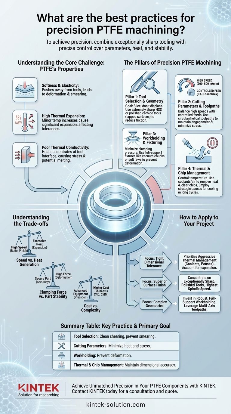
To achieve precision when machining Polytetrafluoroethylene (PTFE), you must combine exceptionally sharp tooling with precise control over cutting parameters, heat generation, and workpiece stability. The core practices involve using HSS or polished carbide tools, maintaining high cutting speeds (200–500 m/min) with controlled feed rates (0.1–0.5 mm/rev), and employing secure, low-pressure fixturing like vacuum chucks to prevent the material from deforming.
The central challenge of machining PTFE is not cutting the material, but managing its unique physical properties. Its softness, poor heat conductivity, and high thermal expansion mean that success depends more on controlling deformation and heat than on aggressive material removal.
Understanding the Core Challenge: PTFE's Properties
To machine PTFE effectively, you must first respect its fundamental characteristics. These properties are advantages in the final application but create significant hurdles during fabrication.
The Impact of Softness and Elasticity
PTFE is an exceptionally soft material that tends to push away from a cutting tool rather than shear cleanly.
Using dull or improperly shaped tools will result in deformation, material smearing, and significant burring instead of a precise cut.
The Problem of High Thermal Expansion
PTFE has a very high coefficient of thermal expansion. Even minor temperature increases from cutting friction can cause the material to expand significantly.
This expansion can throw off critical dimensions, making it difficult to hold tight tolerances if heat is not meticulously managed.
The Challenge of Poor Thermal Conductivity
Unlike metals, PTFE is an excellent thermal insulator. It does not dissipate heat well from the cutting zone.
Heat becomes concentrated at the tool-material interface, quickly leading to thermal expansion, potential melting, and stress on the workpiece.
The Pillars of Precision PTFE Machining
Mastering PTFE requires a holistic approach that addresses the material's properties through four key areas of focus.
Pillar 1: Tool Selection and Geometry
The right tool is the most critical factor. The goal is to slice the material, not displace it.
Use extremely sharp cutting edges. A honed, razor-sharp edge is non-negotiable to prevent pushing and deforming the material.
Select the right tool material. Both High-Speed Steel (HSS) and carbide tools are effective, but carbide tools should have highly polished (lapped) surfaces to reduce friction and material buildup.
Pillar 2: Cutting Parameters and Toolpaths
Your machine settings must be optimized to minimize heat generation and mechanical stress.
Balance high speeds with controlled feeds. Use high cutting speeds (200–500 m/min) to ensure the tool is cutting efficiently, but pair this with a moderate feed rate (0.1–0.5 mm/rev) to prevent excess friction.
Employ strategic toolpaths. Use circular or helical toolpaths to maintain constant tool engagement and minimize vibrations. Avoid aggressive, full-width cuts, especially on thin-walled sections, to reduce stress.
Pillar 3: Workholding and Fixturing
Because PTFE deforms easily, how you hold the workpiece is just as important as how you cut it.
Minimize clamping pressure. Overtightening a standard vise will compress and distort the material, leading to inaccurate final dimensions once the pressure is released.
Provide complete support. Use fixtures that support the entire workpiece, such as vacuum chucks or soft jaws custom-molded to the part's shape, to ensure maximum stability without deformation.
Pillar 4: Thermal and Chip Management
Controlling temperature is essential for maintaining dimensional accuracy.
Use appropriate coolants. Flood coolants or compressed air can help remove heat from the cutting zone and clear away the stringy chips that PTFE often produces.
Consider strategic pauses. For long cutting cycles or deep cuts, programming periodic pauses allows the material to cool and stabilize, preventing heat buildup from compromising tolerances.
Understanding the Trade-offs
Achieving precision with PTFE involves balancing competing factors. Understanding these compromises is key to troubleshooting and process optimization.
Speed vs. Heat Generation
While high cutting speeds promote a better surface finish, pushing them too far without adequate cooling will generate excessive heat, causing the part to expand and go out of tolerance. The optimal speed is often the highest possible before thermal effects become unmanageable.
Clamping Force vs. Part Stability
A secure part prevents chatter and ensures accuracy. However, PTFE's softness means that the force required for stability in metals will cause significant deformation. The goal is to find the minimum clamping force that still eliminates any part movement or vibration.
Cost vs. Complexity
Achieving the highest levels of precision often requires advanced equipment. Multi-axis CNC machines enable complex geometries, and Coordinate Measuring Machines (CMM) are necessary for verifying tight tolerances, adding to the overall cost and complexity of the process.
How to Apply This to Your Project
Your specific machining strategy should be guided by the most critical outcome for your component.
- If your primary focus is tight dimensional tolerance: Prioritize aggressive thermal management using coolants and pauses, and ensure your programmed dimensions account for any potential thermal expansion.
- If your primary focus is superior surface finish: Concentrate on using exceptionally sharp, polished tools at the highest possible spindle speed with a controlled, consistent feed rate.
- If your primary focus is machining complex geometries: Invest in robust, full-support workholding and leverage multi-axis toolpaths that minimize stress and tool changes.
Ultimately, machining PTFE with precision is an exercise in finesse, proving that a deep understanding of the material is the most important tool of all.
Summary Table:
| Key Practice | Primary Goal | Key Consideration |
|---|---|---|
| Tool Selection & Geometry | Clean shearing, prevent smearing | Use extremely sharp HSS or polished carbide tools. |
| Cutting Parameters | Minimize heat and stress | High speeds (200-500 m/min), controlled feeds (0.1-0.5 mm/rev). |
| Workholding & Fixturing | Prevent deformation | Use low-pressure, full-support methods like vacuum chucks. |
| Thermal & Chip Management | Maintain dimensional accuracy | Employ coolants/air and strategic pauses to control heat. |
Achieve Unmatched Precision in Your PTFE Components with KINTEK
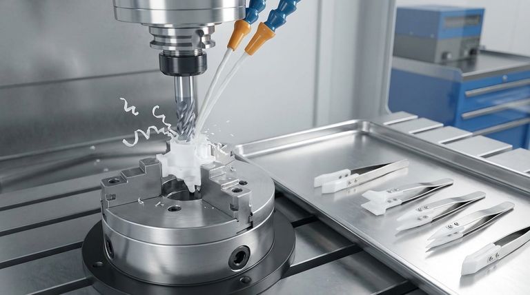
Machining PTFE to exacting standards requires specialized expertise and a focus on finesse over force. At KINTEK, we manufacture precision PTFE components—including seals, liners, and custom labware—for the semiconductor, medical, laboratory, and industrial sectors. We master the critical balance of sharp tooling, precise parameters, and secure fixturing to deliver parts with exceptional dimensional accuracy and surface finishes, from prototypes to high-volume production runs.
Let us apply our deep material knowledge to your most challenging projects. Contact KINTEK today for a consultation and quote.
Visual Guide
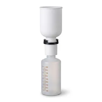
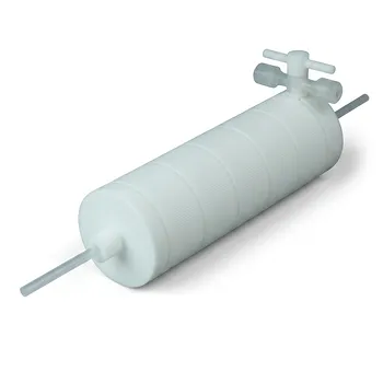
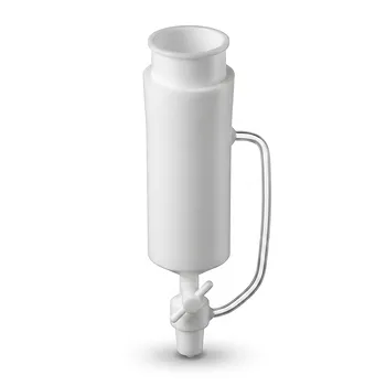
Related Products
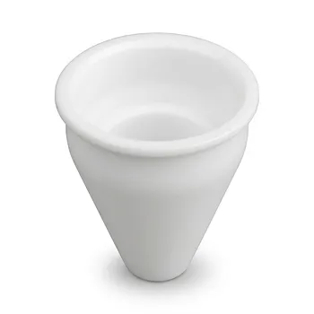
- Custom Machined PTFE Conical Sample Cell Corrosion Resistant Triangular Fluoropolymer Container for Trace Analysis
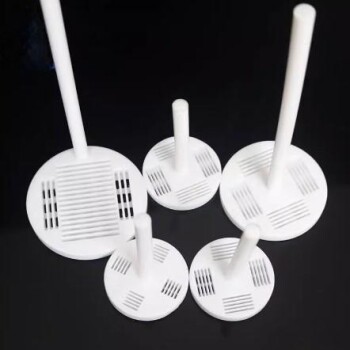
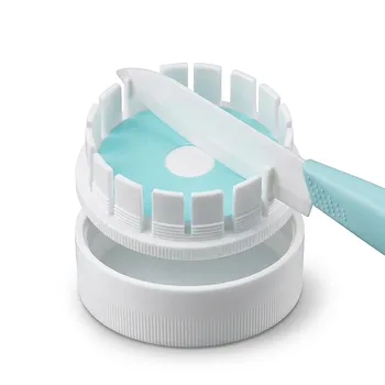
- Custom Machined Molded PTFE Teflon Parts Manufacturer for Laboratory ITO FTO Conductive Glass Cleaning Flower Basket
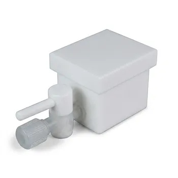
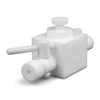
- Custom PTFE Laboratory Apparatus Corrosion Resistant Low Background Reaction Cells Precision CNC Fabrication
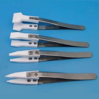
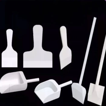
- Custom PTFE Parts Manufacturer for Teflon Parts and PTFE Tweezers
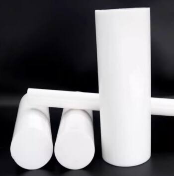
- Customizable PTFE Rods for Advanced Industrial Applications
People Also Ask
- What customization options are available for PTFE materials? Tailor Performance for Your Application
- Can PTFE parts be customized according to specific requirements? Achieve Precision Custom PTFE Components
- What are the advantages of machining PTFE over other materials? Unlock Superior Performance in Harsh Environments
- Can machined PTFE parts be customized? Achieve Precision Solutions for Demanding Applications
- How are PTFE laboratory containers and apparatus typically manufactured? Inside the Precision Machining Process