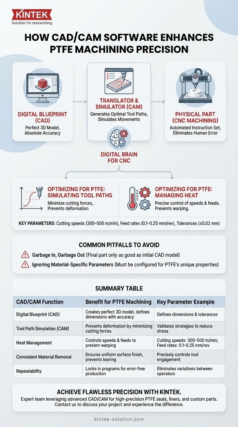
In essence, CAD/CAM software serves as the digital brain for the CNC machine. It enhances the precision of PTFE parts by translating a perfect, dimensionally accurate 3D model directly into a set of explicit instructions for the machine. This automated process removes the potential for human error in interpreting drawings and ensures every cut, hole, and contour precisely matches the original design specifications.
While CAD creates the perfect digital blueprint, it is the CAM software that truly unlocks precision for a challenging material like PTFE. It allows engineers to pre-plan and simulate every machine movement, optimizing for PTFE's unique tendency to deform under heat and pressure before any physical material is ever cut.
From Digital Blueprint to Physical Part
The core function of CAD/CAM is to create a seamless and error-free link between the design intent and the manufacturing output. This is achieved through a two-stage process.
The Role of Computer-Aided Design (CAD)
The process begins with a CAD model. This is a mathematically perfect 3D representation of the final part.
Every dimension, tolerance, and geometric feature is defined with absolute accuracy in this digital environment. This model serves as the single source of truth for the entire manufacturing process.
The Role of Computer-Aided Manufacturing (CAM)
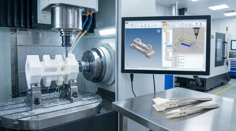
CAM software acts as the translator. It takes the perfect CAD model and generates the optimal tool paths and corresponding machine language (G-code) needed to create it.
This is not just a simple conversion. The CAM system allows the engineer to define critical variables like the type of cutting tool, the speed of the cut, and the feed rate—all of which are vital for machining a soft material like PTFE.
Eliminating Human Interpretation
Prior to integrated CAD/CAM systems, a machinist would interpret a 2D drawing, manually inputting coordinates and making decisions on the fly.
This introduced significant potential for error. By automating the instruction set, CAM ensures that the machine executes the design exactly as intended, every single time.
Optimizing for PTFE's Unique Challenges
Polytetrafluoroethylene (PTFE) is notoriously difficult to machine due to its softness, high thermal expansion rate, and low thermal conductivity. CAD/CAM software provides the digital tools needed to overcome these specific material challenges.
Simulating and Controlling Tool Paths
CAM allows for the simulation of complex tool paths that minimize cutting forces. This prevents the PTFE from deforming or "pushing away" from the tool, which would otherwise compromise dimensional accuracy.
Engineers can test different strategies virtually to find the one that produces the least stress on the material.
Managing Heat Generation
Heat is the enemy of precision when machining PTFE. CAM software allows for precise control of cutting speeds (300–500 m/min) and feed rates (0.1–0.25 mm/rev) to minimize friction and heat buildup.
Tool paths can be specifically designed to allow the material and tool to cool, preventing warping and ensuring tight tolerances (e.g., ±0.02 mm) can be held.
Ensuring Consistent Material Removal
The software calculates and controls the exact amount of material the cutting tool is engaged with at all times.
This consistency is critical for achieving a uniform surface finish and preventing the tool from "grabbing" or tearing the soft PTFE material, which is a common cause of defects.
Common Pitfalls to Avoid
While powerful, CAD/CAM is a tool, not a complete solution. Its precision is dependent on the quality of the inputs and the physical machine setup.
The "Garbage In, Garbage Out" Principle
The final part will only be as accurate as the initial CAD model. Any error or oversight in the design phase will be perfectly and precisely replicated by the CNC machine.
Ignoring Material-Specific Parameters
Using default CAM settings intended for metals like aluminum will lead to disastrous results with PTFE. The software must be configured with the correct parameters for PTFE's unique properties to avoid melting, warping, and poor surface finish.
Overlooking the Physical Environment
The digital precision of a CAM program is useless if the physical setup is flawed. Factors like using dull or incorrect cutting tools (sharp HSS or carbide are required), improper workholding (fixtures), or a poorly calibrated machine will undermine any software-driven accuracy.
Making the Right Choice for Your Goal
To maximize the benefits of CAD/CAM for your PTFE components, tailor your approach to your primary objective.
- If your primary focus is achieving the tightest possible tolerances: Use CAM simulation extensively to validate that your chosen tool paths and cutting parameters actively minimize heat generation and cutting forces.
- If your primary focus is repeatability across a large production run: Lock down the finalized CAD model and CAM program to serve as the single, unchangeable source of truth, eliminating process variations between shifts or operators.
- If your primary focus is manufacturing complex geometries: Leverage your CAM software's advanced tool path strategies (e.g., 5-axis machining) to create smooth, precise contours that are impossible to program manually.
Ultimately, mastering CAD/CAM transforms the challenge of machining PTFE from an art reliant on operator skill into a highly precise and repeatable science.
Summary Table:
| CAD/CAM Function | Benefit for PTFE Machining | Key Parameter Example |
|---|---|---|
| Digital Blueprint (CAD) | Creates a mathematically perfect 3D model | Defines dimensions and tolerances with absolute accuracy |
| Tool Path Simulation (CAM) | Prevents deformation by minimizing cutting forces | Validates strategies to reduce stress on soft PTFE |
| Heat Management | Controls speeds and feeds to prevent warping | Cutting speeds: 300–500 m/min; Feed rates: 0.1–0.25 mm/rev |
| Consistent Material Removal | Ensures uniform surface finish and prevents tearing | Precisely controls tool engagement with PTFE |
| Repeatability | Locks in programs for error-free production runs | Eliminates variations between operators or shifts |
Ready to achieve flawless precision for your PTFE components?
At KINTEK, we specialize in manufacturing high-precision PTFE seals, liners, labware, and custom parts for the semiconductor, medical, laboratory, and industrial sectors. Our expert team leverages advanced CAD/CAM software to transform your designs into perfectly machined parts, ensuring tight tolerances (like ±0.02 mm) and optimal performance—from prototypes to high-volume orders.
Contact us today to discuss your project and experience the KINTEK difference! Get in touch via our contact form.
Visual Guide
Related Products
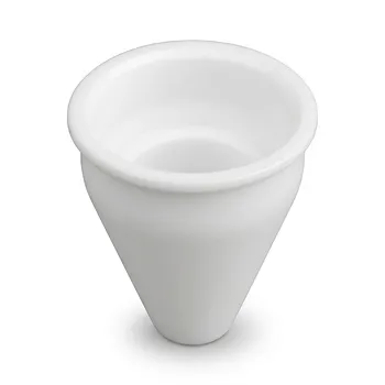
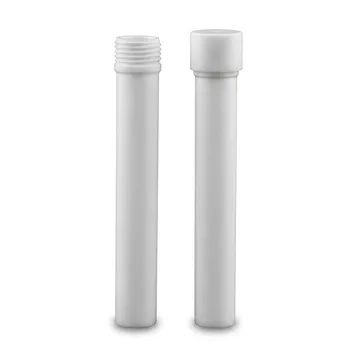
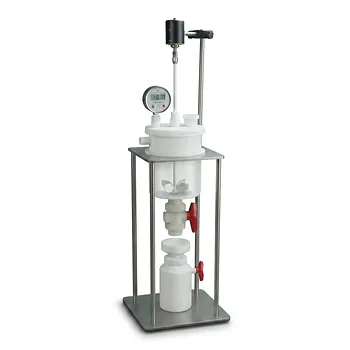
- Custom Machined PTFE Conical Sample Cell Corrosion Resistant Triangular Fluoropolymer Container for Trace Analysis
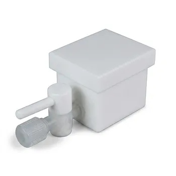
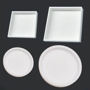
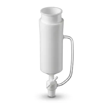
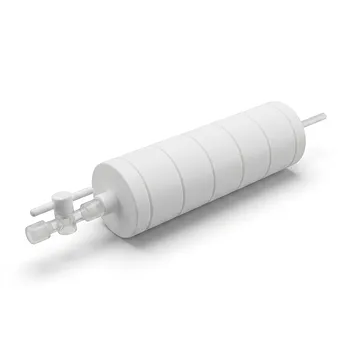
- Custom PTFE Laboratory Apparatus Corrosion Resistant Low Background Reaction Cells Precision CNC Fabrication
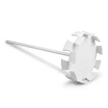
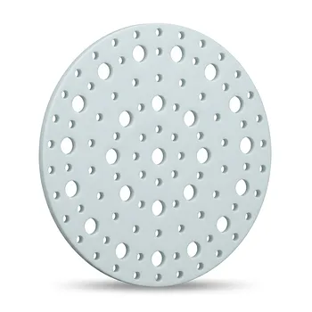
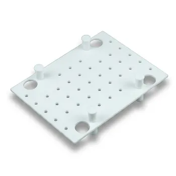
- PTFE Dispersion Disk Food Cosmetic Grade Non Stick Corrosion Resistant Large Stirring Paddle Customizable Impeller
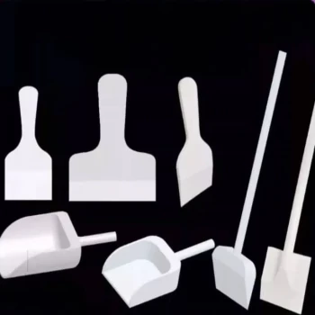
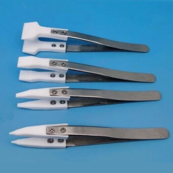
- Customizable PTFE Scrapers and Shovels for Demanding Applications
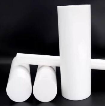
- Customizable PTFE Rods for Advanced Industrial Applications
People Also Ask
- Can machined PTFE parts be customized? Achieve Precision Solutions for Demanding Applications
- Why is machined PTFE popular in the medical field? Unmatched Biocompatibility & Precision
- How do Polytetrafluoroethylene (PTFE) containers perform regarding gas permeation? Expert Insights on Solvent Absorption
- What are the advantages of machining PTFE over other materials? Unlock Superior Performance in Harsh Environments
- Can PTFE parts be customized according to specific requirements? Achieve Precision Custom PTFE Components