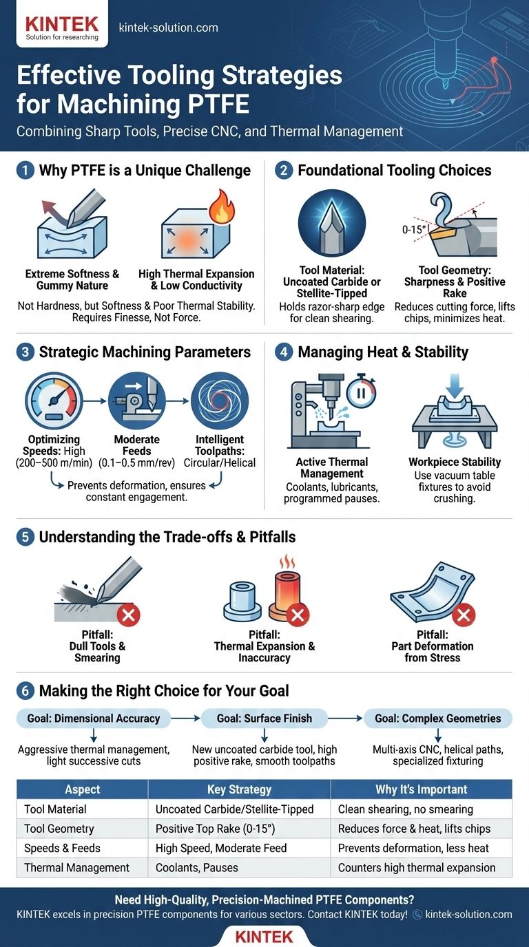
To effectively machine PTFE, the ideal strategy combines extremely sharp, uncoated carbide or Stellite-tipped cutting tools with a positive top rake. This tooling must be paired with precise CNC control that manages cutting speeds, feed rates, and toolpaths to minimize heat generation and physical deformation of the material.
The core challenge in machining PTFE is not its hardness, but its softness and poor thermal stability. A successful tooling strategy is therefore less about aggressive material removal and more about finesse—using exceptionally sharp tools to slice the material cleanly without generating the heat and cutting pressure that cause it to deform and warp.
Why PTFE Presents a Unique Machining Challenge
Polytetrafluoroethylene (PTFE) has properties that make it notoriously difficult to machine accurately. Understanding these properties is the first step toward selecting the right tooling and strategy.
Extreme Softness and "Gummy" Nature
PTFE is a very soft polymer that tends to push away from a cutting tool rather than shearing cleanly. A dull or improperly shaped tool will smear or tear the material, resulting in a poor surface finish and burrs.
High Thermal Expansion
The material expands and contracts significantly with temperature changes. Heat generated during machining can cause the workpiece to distort, leading to severe dimensional inaccuracy once it cools.
Low Thermal Conductivity
PTFE does not dissipate heat well. Frictional heat generated at the cutting edge concentrates in a small area, exacerbating the problem of thermal expansion and potentially damaging the material's integrity.
Foundational Tooling Choices
Your choice of tool material and geometry is the single most important factor for success. The goal is to create a shearing action, not a plowing one.
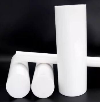
Tool Material: Uncoated Carbide is the Standard
Uncoated carbide or Stellite-tipped tools are the preferred choice. Their ability to hold a razor-sharp edge is paramount for cleanly slicing through the soft material. Avoid coated tools, as the coatings are often not as sharp as the bare substrate.
Tool Geometry: Sharpness and Positive Rake
A positive top rake, typically between 0 and 15 degrees, is crucial. This geometry reduces cutting forces, lifts the chip away from the workpiece, and minimizes the "plowing" effect that generates excess heat and deforms the material.
Tool Maintenance: Sharpness is Non-Negotiable
PTFE will dull even carbide tools over time. Dull tools immediately increase cutting pressure and heat. Tools must be inspected frequently and resharpened or replaced to maintain performance.
Strategic Machining Parameters and Techniques
With the right tools selected, the focus shifts to how you use them. Your CNC programming and machine setup are critical for managing the unique challenges of PTFE.
Optimizing Speeds and Feeds
Maintain high cutting speeds (typically 200–500 m/min) to help the tool get "ahead" of material deformation. Pair this with moderate feed rates (0.1–0.5 mm/rev) to prevent overwhelming the cutting edge and generating excess pressure.
The Role of Intelligent Toolpaths
Use circular or helical toolpaths whenever possible, especially for milling. These paths ensure constant tool engagement, which minimizes vibration and provides a more consistent surface finish. Avoid full-width cuts on thin sections to reduce stress and prevent the part from flexing away from the tool.
Managing Heat and Stability
Actively manage temperature. Using a coolant or lubricant can help, but sometimes periodic pauses in the program are necessary to allow the part to cool and stabilize. Furthermore, workpiece stability is key. Use fixtures, such as a vacuum table, that secure the part firmly without the clamping pressure that could crush or deform it.
Understanding the Trade-offs and Pitfalls
Ignoring the principles of PTFE machining leads to predictable failures. Being aware of these common pitfalls helps reinforce the importance of the correct strategy.
Pitfall: Dull Tools and Material Smearing
Using a tool that isn't exceptionally sharp will cause it to plow through the PTFE. This generates extreme frictional heat, smears the material instead of cutting it, and leaves a rough, burr-heavy surface finish.
Pitfall: Thermal Expansion and Inaccuracy
If your speeds are too high or your cuts too heavy, the part will heat up and expand. You might machine it to the correct dimension while it's hot, but it will be undersized once it cools to room temperature.
Pitfall: Part Deformation from Stress
Aggressive cuts or improper work-holding introduces stress into the material. This is especially problematic with thin-walled features, which can easily warp during or after the machining process.
Making the Right Choice for Your Goal
Select your primary focus to fine-tune your approach for the best possible outcome.
- If your primary focus is dimensional accuracy: Prioritize aggressive thermal management through coolants or programmed pauses, and use light, successive cuts rather than a single heavy one.
- If your primary focus is surface finish: Use a brand new or freshly ground uncoated carbide tool with a high positive rake and ensure your toolpaths are smooth and continuous.
- If your primary focus is machining complex geometries: Rely on a multi-axis CNC to enable helical toolpaths and minimize stress on delicate features, and use specialized fixturing to support the part without distortion.
By treating PTFE with the finesse it requires, you can move past its challenges and consistently produce clean, accurate, and high-quality components.
Summary Table:
| Aspect | Key Strategy | Why It's Important |
|---|---|---|
| Tool Material | Uncoated carbide or Stellite-tipped | Holds a razor-sharp edge for clean shearing, not smearing. |
| Tool Geometry | Positive top rake (0-15°) | Reduces cutting forces and heat generation, lifting chips away. |
| Speeds & Feeds | High speed (200-500 m/min), moderate feed (0.1-0.5 mm/rev) | Prevents material from deforming and minimizes heat buildup. |
| Thermal Management | Coolants, lubricants, or programmed pauses | Counters PTFE's high thermal expansion and low conductivity. |
Need High-Quality, Precision-Machined PTFE Components?
Machining PTFE to exact specifications requires specialized expertise and the right tooling strategy. KINTEK excels at manufacturing precision PTFE components—including seals, liners, and custom labware—for the semiconductor, medical, laboratory, and industrial sectors.
We combine advanced CNC techniques with a deep understanding of material science to deliver components with superior dimensional accuracy and surface finish, from prototypes to high-volume orders.
Contact KINTEB today to discuss your PTFE machining project and get a quote!
Visual Guide
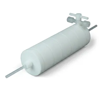
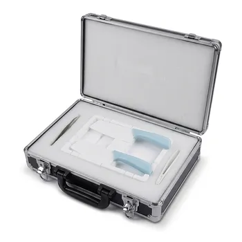
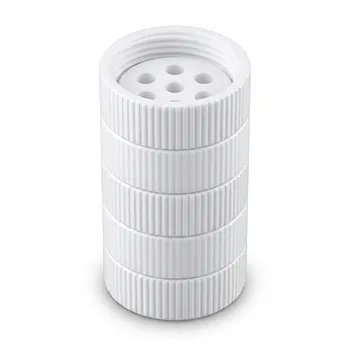
Related Products
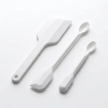
- Custom PTFE Scraper Shovel and Sampling Spoon Dual Use Corrosion Resistant Low Background White Fluoropolymer Tool
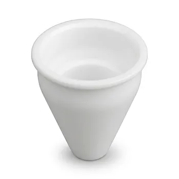
- Custom Machined PTFE Conical Sample Cell Corrosion Resistant Triangular Fluoropolymer Container for Trace Analysis
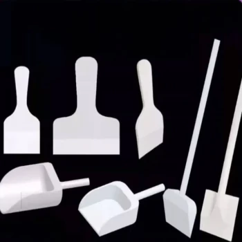
- Customizable PTFE Scrapers and Shovels for Demanding Applications
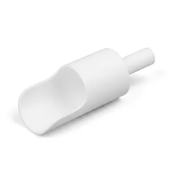
- Custom Food Grade PTFE Scoops Cylindrical Chemical Spatulas Bio Pharmaceutical Non Polluting Material Handling Tools
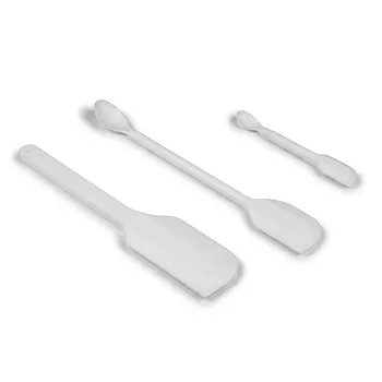
- Custom PTFE Double Headed Lab Spatula Chemical Resistant Non Stick Pharmaceutical Grade Fluoropolymer Sampling Tool
People Also Ask
- Why are PTFE shovels considered cost-effective? Maximize ROI with Superior Durability
- Why are PTFE shovels considered biocompatible? Ensure Sample Purity and Safety
- How does the durability of PTFE shovels compare to plastic shovels? Discover the Superior Choice for Harsh Conditions
- What are the advantages of PTFE shovels in terms of chemical resistance? Unmatched Inertness for Handling Corrosives
- What are the advantages of PTFE shovels over metal shovels? Precision Handling for Sensitive Materials