Lateral movement in PTFE sliding bearings is restricted by integrating mechanical guides into the bearing assembly. The two primary methods for achieving this are installing guide plates along the sides of the bearing or using dowel pins on one element that fit into corresponding longitudinal slots on the other, effectively creating a track that permits only single-axis motion.
The core principle is that a basic PTFE bearing is inherently a free-floating, low-friction surface. To be useful in most structural applications, this freedom must be constrained to a specific direction, which is accomplished by adding robust mechanical guides that channel the movement and prevent unwanted lateral shifts.
The Default State: Unrestrained Movement
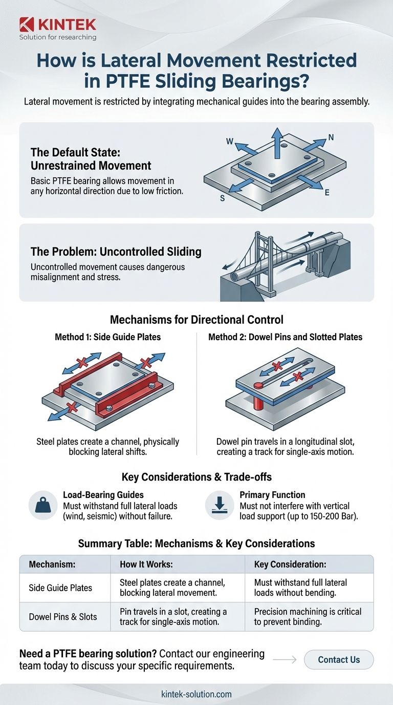
A standard PTFE sliding bearing is designed for one primary purpose: to create a surface with an extremely low coefficient of friction. Without additional components, this surface allows movement in any horizontal direction.
How a Basic PTFE Bearing Works
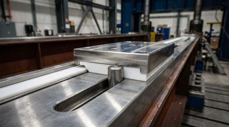
The assembly consists of a PTFE sheet, often with fillers to improve its mechanical properties, bonded to a steel backing plate. This PTFE surface slides against a highly polished stainless steel plate, which is typically welded to the opposing structural element. This arrangement is designed to support significant vertical loads while allowing nearly frictionless horizontal movement.
The Problem with Uncontrolled Sliding
In applications like bridges, pipelines, or large buildings, movement is rarely random. It is typically a predictable result of thermal expansion and contraction along a specific axis. Uncontrolled lateral (transverse) movement can cause dangerous misalignment, introduce unintended stress into the structure, and defeat the purpose of the bearing.
Mechanisms for Enforcing Directional Control
To ensure movement only occurs where intended, engineers add physical restraints to the bearing assembly. These restraints must be strong enough to withstand any anticipated side loads.
Method 1: Side Guide Plates
This straightforward approach involves fixing steel guide plates or bars along the sides of the sliding element. These plates act as physical barriers, forming a channel that forces the bearing to move only in the longitudinal direction. The clearance between the sliding plate and the guides is kept to a minimum to prevent play.
Method 2: Dowel Pins and Slotted Plates
Another common method uses one or more steel dowel pins fixed to the lower bearing plate. These pins engage with a precisely machined longitudinal slot in the upper plate. The pin is free to travel along the length of the slot but is physically blocked from moving side-to-side, restricting all movement to a single axis.
The Importance of Load-Bearing Guides
It is critical to recognize that these guiding components are not merely for alignment. They are structural elements that must be designed to absorb the full force of any expected lateral loads—such as wind, seismic activity, or braking forces—without bending, shearing, or failing.
Understanding the Trade-offs and Design Constraints
While restricting movement is essential, it introduces additional design considerations. The primary function of the bearing must not be compromised.
Primary Function: Vertical Load Support
A PTFE bearing's first job is to support vertical compressive loads. The size of the PTFE pad is calculated based on this load, typically using a working pressure of 150-200 Bar (15-20 MPa) to maintain a significant safety factor. The guiding mechanisms are secondary features that must not interfere with this primary load-bearing capacity.
Accommodating Rotation vs. Translation
Directional guides are excellent for controlling horizontal translation, but they do not address rotation. If minor rotational misalignment is expected, an elastomeric pad (like neoprene) can be incorporated into the assembly. For significant rotation, a completely different design, such as a spherical bearing, may be required.
The Risk of Binding and Increased Friction
If guides are improperly designed or installed with insufficient clearance, they can bind against the sliding element. This can dramatically increase the coefficient of friction, causing the bearing to jam and transfer unintended stress into the superstructure. Proper fabrication and alignment are therefore paramount.
Making the Right Choice for Your Goal
Selecting the correct bearing configuration depends entirely on the specific movements you need to allow and restrict for your structure.
- If your primary focus is predictable, single-axis movement: A guided bearing using either dowel pins or side plates is the correct choice to accommodate thermal expansion.
- If your primary focus is accommodating minor angular misalignment: Your specification should include an elastomeric element in addition to any directional guides needed for translation.
- If your primary focus is allowing free radial expansion: An unguided (free-floating) bearing is appropriate for applications like circular tanks where movement occurs in all directions from a central point.
By understanding these control mechanisms, you can ensure your chosen PTFE bearing provides the precise degree of freedom your structure requires.
Summary Table:
| Mechanism | How It Works | Key Consideration |
|---|---|---|
| Side Guide Plates | Steel plates fixed along the sides create a channel, physically blocking lateral movement. | Must withstand full lateral loads (wind, seismic) without bending. |
| Dowel Pins & Slots | A pin on one plate travels in a longitudinal slot on the other, creating a track for single-axis motion. | Precision machining is critical to prevent binding and increased friction. |
Need a PTFE bearing solution that provides precise directional control for your structure?
At KINTEK, we specialize in manufacturing high-performance PTFE components, including custom sliding bearings for the semiconductor, medical, laboratory, and industrial sectors. Our expertise in precision production ensures your bearings will reliably restrict lateral movement while supporting critical vertical loads—from initial prototypes to high-volume orders.
Contact our engineering team today to discuss your specific requirements and get a solution tailored for your project's success.
Visual Guide
Related Products
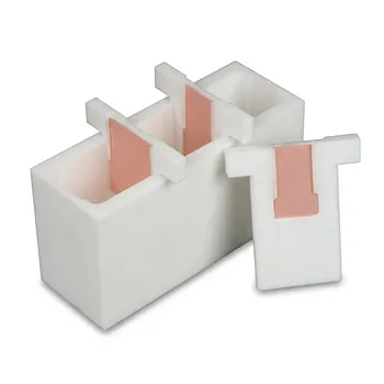
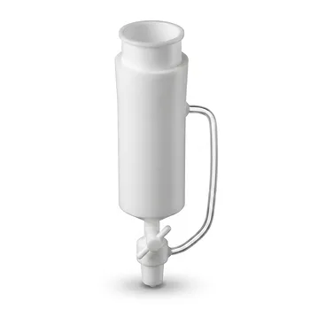
- White PTFE Electrolytic Cell with Movable Slider and Insulated Lid for Fluorine Corrosion Resistance
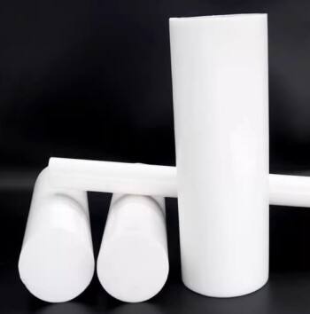
- Customizable PTFE Rods for Advanced Industrial Applications
- Custom Graphite Filled PTFE Rods for Advanced Industrial Applications
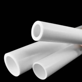
- Custom PTFE Sleeves and Hollow Rods for Advanced Applications
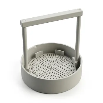
- Custom PTFE Acid Resistant Support Rack for PFA Hydrogen Absorption Systems Multi Hole Configurations
People Also Ask
- How does the hydrophobicity of PTFE benefit electrochemical measurements? Enhance Stability and Precision in Your Lab
- What are the primary components required for the construction of a standard electrolytic cell? Essential Hardware Guide
- How does the use of electrolytic cells benefit electroplating and surface finishing applications? Precision & Durability
- What is the fundamental operating principle of an electrolytic cell? Master Energy-Driven Redox Reactions
- What are the advantages of using electrolytic cells for refining non-ferrous metals like copper and zinc? 99.99% Purity