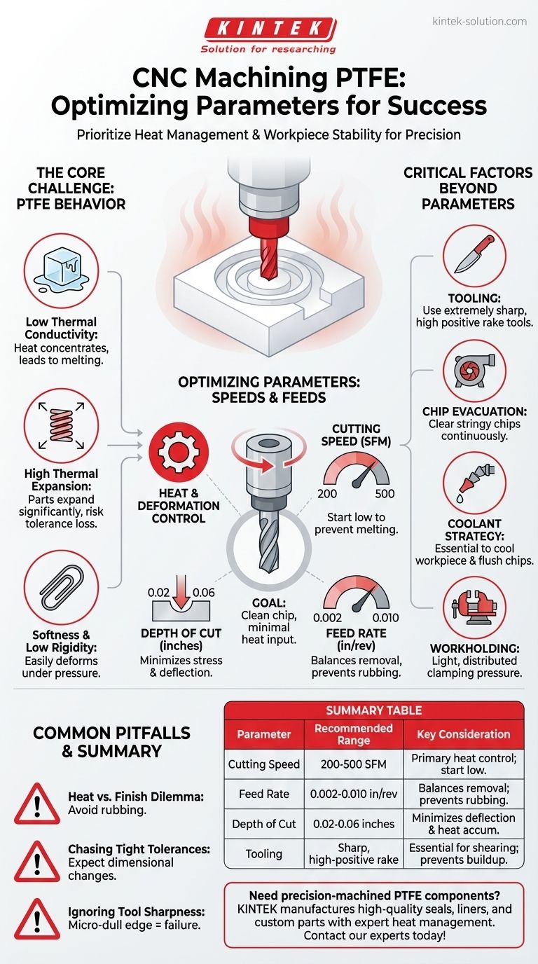
To successfully machine Polytetrafluoroethylene (PTFE), you must prioritize heat management and workpiece stability over aggressive material removal. The recommended starting parameters are a cutting speed between 200-500 Surface Feet per Minute (SFM), a feed rate of 0.002-0.010 inches per revolution, and a shallow depth of cut between 0.02-0.06 inches.
The central challenge in machining PTFE is not its hardness, but its unique combination of softness, low thermal conductivity, and high thermal expansion. Your success depends entirely on a strategy that minimizes heat generation and physical deformation at every stage of the process.
The Core Challenge: Understanding PTFE's Behavior
Machining PTFE is less about brute force and more about finesse. Unlike metals, PTFE's properties create a unique set of challenges that dictate a specific approach. Understanding these properties is the key to achieving accurate, high-quality parts.
Softness and Low Rigidity
PTFE is a soft material that can easily deform under pressure. Aggressive clamping or excessive tool pressure will compress or distort the workpiece, making it impossible to hold tight tolerances.
Low Thermal Conductivity
This is the most critical property to manage. PTFE does not dissipate heat well. Any heat generated by friction at the cutting edge will concentrate in a small area, quickly leading to melting rather than clean cutting.
High Thermal Expansion
When PTFE does heat up, it expands significantly more than metals. Even a minor temperature increase can cause the part to go out of tolerance, only to shrink back after it cools, resulting in an undersized feature.
Optimizing Your Machining Parameters
Your speeds and feeds must be set with the express purpose of controlling the factors listed above. The goal is to create a clean chip with minimal heat input.
Cutting Speed: The Primary Heat Control
Cutting speed is directly related to frictional heat. While some sources suggest higher speeds are possible, a conservative starting point of 200-500 SFM is recommended to prevent melting and material buildup on the tool.
Always start on the lower end of the range and observe the cut. If you see any signs of melting or a "gummy" texture, reduce your speed immediately.
Feed Rate: Balancing Removal and Finish
A feed rate of 0.002 to 0.010 inches per revolution (or 0.1–0.2 mm/rev) strikes the right balance. A feed rate that is too low will cause the tool to rub instead of cut, generating excess heat.
A moderately high feed rate within this range produces a thicker chip that helps carry heat away from the workpiece, resulting in a cleaner, cooler cut.
Depth of Cut: Minimizing Stress
Keep your depth of cut shallow, typically between 0.02 and 0.06 inches (0.5–1.5 mm). A smaller depth minimizes the cutting force, reducing the risk of part deflection and heat accumulation. This is crucial for maintaining accuracy and achieving a good surface finish.
Critical Factors Beyond Speeds and Feeds
Achieving success with PTFE requires looking beyond the basic parameters. Your tooling, coolant strategy, and workholding are just as important.
Tooling is Non-Negotiable
Use extremely sharp cutting tools, preferably those designed for plastics or aluminum. A high positive rake angle and polished flutes will produce a shearing action and help prevent chips from sticking. A dull tool will plow through and rub the material, guaranteeing failure.
Effective Chip Evacuation
PTFE produces long, stringy chips (swarf) that can wrap around the tool and workpiece, causing heat buildup and marring the surface finish. Ensure there is sufficient tool clearance and consider using directed air or coolant to clear chips away from the cutting zone continuously.
Coolant Strategy
For any operation that generates significant heat, a coolant system is essential. The primary purpose of the coolant is to cool the workpiece and flush away chips. Standard flood coolant works well for this.
Workholding and Clamping Pressure
Apply just enough clamping pressure to hold the workpiece securely. Use soft jaws or distribute the clamping force over a larger area to avoid distorting the raw material before you even begin machining.
Understanding the Common Pitfalls
Even with the right parameters, certain challenges are inherent to working with PTFE. Being aware of them allows you to anticipate and mitigate potential problems.
The Heat vs. Finish Dilemma
While high speeds generate heat, going too slow with a low feed rate can cause the tool to simply rub against the material. This burnishing action also creates significant heat and results in a poor surface finish. You must find the sweet spot where the tool is consistently forming a chip.
Chasing Tight Tolerances
PTFE's resilience and thermal expansion make holding extremely tight tolerances (e.g., +/- 0.002 inches) a task for skilled machinists. Expect some dimensional change as the part cools to room temperature. Always measure parts after they have stabilized.
Ignoring Tool Sharpness
This is the most common mistake. A cutting edge that feels sharp enough for aluminum may not be sharp enough for PTFE. A microscopic dull edge will immediately begin rubbing and melting the material. When in doubt, use a fresh, sharp tool.
How to Apply This to Your Project
Your specific parameters will be a function of your primary goal. Use these recommendations as a starting point and adjust based on observation.
- If your primary focus is dimensional accuracy: Prioritize low cutting speeds, shallow depths of cut, and consistent cooling to manage thermal expansion.
- If your primary focus is surface finish: Use extremely sharp, polished tools with a high positive rake and ensure your feed rate is sufficient to cut cleanly without rubbing.
- If your primary focus is rapid material removal (roughing): Use the higher end of the recommended feed rate and depth of cut, but keep cutting speeds moderate and ensure excellent chip evacuation.
By managing heat and deformation as your top priorities, you can machine PTFE with predictable, high-quality results.
Summary Table:
| Parameter | Recommended Range | Key Consideration |
|---|---|---|
| Cutting Speed | 200-500 SFM | Primary control for frictional heat; start low to prevent melting. |
| Feed Rate | 0.002-0.010 in/rev | Balances material removal and finish; prevents rubbing. |
| Depth of Cut | 0.02-0.06 inches | Minimizes part deflection and heat accumulation. |
| Tooling | Sharp, high-positive rake | Essential for a clean shearing cut; prevents material buildup. |
Need precision-machined PTFE components? Machining PTFE requires specialized expertise to manage its unique properties like low thermal conductivity and high expansion. KINTEK manufactures high-quality PTFE seals, liners, labware, and custom components for the semiconductor, medical, laboratory, and industrial sectors. We prioritize precision production, from prototypes to high-volume orders, ensuring your parts meet exact specifications. Contact our experts today to discuss your project and get a quote!
Visual Guide
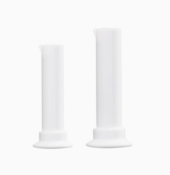
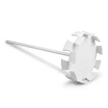
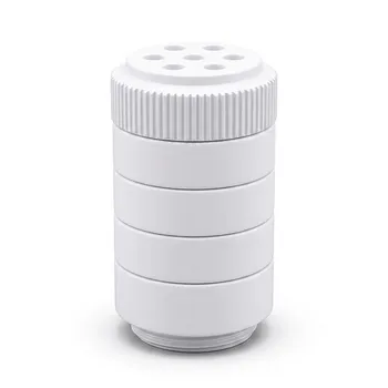
Related Products
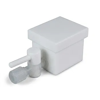
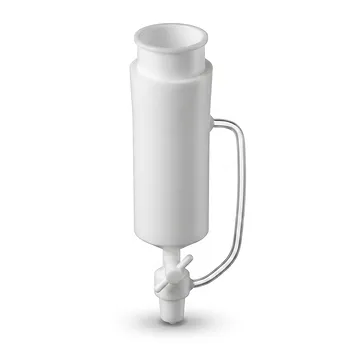
- Custom PTFE Laboratory Apparatus Corrosion Resistant Low Background Reaction Cells Precision CNC Fabrication
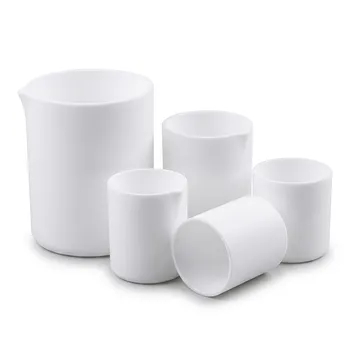
- Large Scale PTFE Beakers and Flasks for High Temperature Corrosion Resistant Laboratory Applications with Custom CNC Fabrication
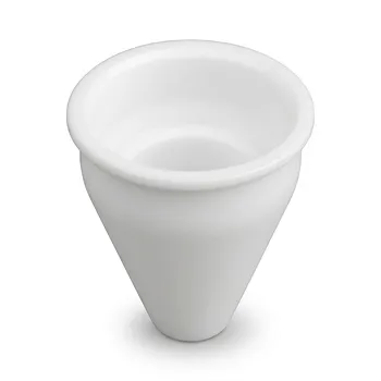
- Custom Machined PTFE Conical Sample Cell Corrosion Resistant Triangular Fluoropolymer Container for Trace Analysis
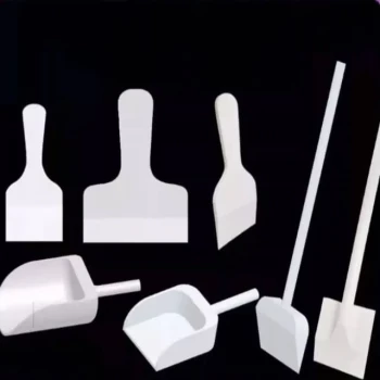
- Customizable PTFE Scrapers and Shovels for Demanding Applications
- Custom PTFE Constant Pressure Separatory Funnel Corrosion Resistant Low Background Labware for PFA Flasks
People Also Ask
- What is the chemical compatibility range for PTFE laboratory apparatus? Explore Near-Universal Chemical Resistance.
- What are the primary chemical resistance properties of PTFE laboratory apparatus? Unmatched Purity and Inertness
- What customization options are available for PTFE materials? Tailor Performance for Your Application
- What are the primary fabrication methods for PTFE laboratory apparatus? Expert Insights into Fluoropolymer Engineering
- What types of finished products are made from PTFE? Seals, Bearings, Labware & More