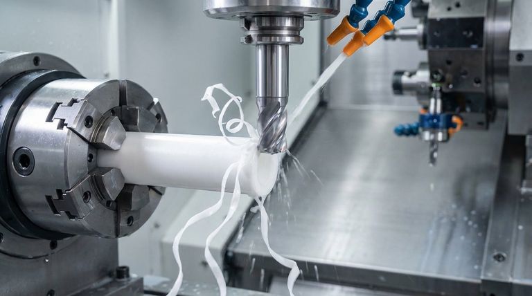
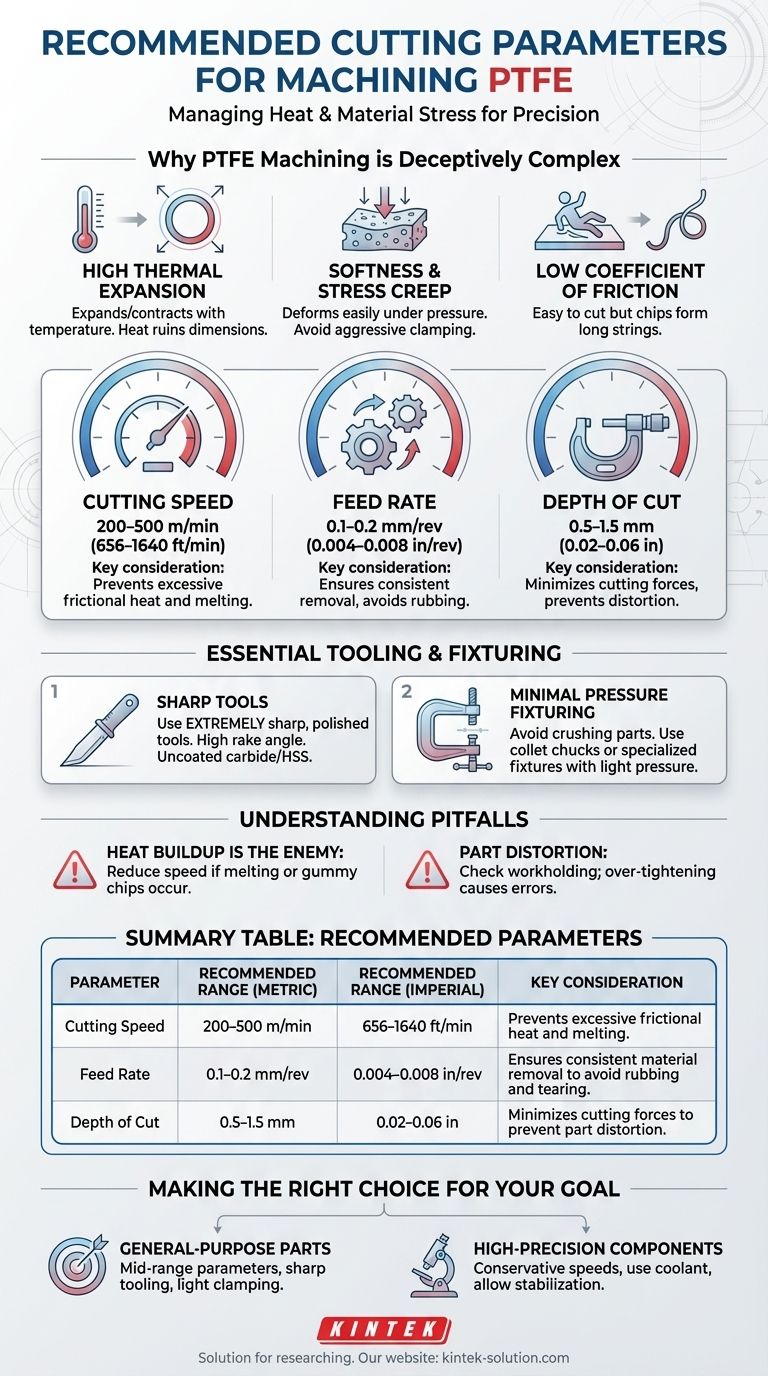
For machining PTFE, the recommended parameters are a cutting speed of 200–500 m/min (656–1640 ft/min), a feed rate of 0.1–0.2 mm/rev (0.004–0.008 in/rev), and a shallow depth of cut between 0.5–1.5 mm (0.02–0.06 in). These settings are designed to manage heat generation and minimize material stress, which are the primary challenges when working with this material.
The central challenge in machining PTFE is not the cutting process itself, which is quite easy, but rather controlling the material's response to heat and pressure. Success depends less on hitting exact numbers and more on understanding how PTFE's unique properties—like high thermal expansion and softness—impact dimensional accuracy.
Why PTFE Machining is Deceptively Complex
While PTFE's softness and low friction make it seem simple to machine, its inherent characteristics introduce unique challenges. Mastering these properties is the key to producing accurate parts.
High Coefficient of Thermal Expansion
PTFE expands and contracts significantly with temperature changes. The friction from cutting generates heat, which can cause the material to expand during the operation and shrink as it cools, ruining your final dimensions.
This property is the primary reason for using moderate cutting speeds and sharp tools—to minimize heat buildup.
Softness and Stress Creep
PTFE is a soft material that can easily deform or compress under pressure. Aggressive clamping or heavy cutting forces will distort the workpiece, leading to inaccuracies.
The material can also "creep," or slowly deform over time when under a constant load, which makes secure, non-damaging fixturing a critical concern.
Low Coefficient of Friction
This well-known property makes PTFE easy to cut with minimal force. However, it also means that chips do not break easily, often forming long, continuous strings that can wrap around the tool and workpiece.
The Recommended Machining Parameters Explained
The standard parameters are a starting point designed to balance speed with quality by mitigating the material's natural tendencies.
Cutting Speed: 200–500 m/min (656–1640 ft/min)
This range is fast enough for efficient material removal but slow enough to prevent excessive frictional heat. Exceeding this speed risks melting the PTFE, leading to a poor surface finish and dimensional instability.
Feed Rate: 0.1–0.2 mm/rev (0.004–0.008 in/rev)
A steady, moderate feed rate ensures the tool is constantly engaged in cutting rather than rubbing against the material. This consistent removal prevents unnecessary heat generation and material tearing.
Depth of Cut: 0.5–1.5 mm (0.02–0.06 in)
Shallow cuts minimize the cutting forces exerted on the material. This is crucial for preventing the soft PTFE from flexing, distorting, or being pushed away from the tool, which would compromise accuracy.
Essential Tooling and Fixturing
Your setup is as important as your cutting parameters. The right tools and workholding methods are non-negotiable for achieving precision.
Choosing the Right Cutting Tools
Always use extremely sharp and polished cutting tools. Uncoated carbide or High-Speed Steel (HSS) tools with a high rake angle and significant relief are ideal.
A sharp edge shears the material cleanly rather than plowing through it, which dramatically reduces heat and cutting pressure.
Fixturing with Minimal Pressure
Avoid standard vise jaws that can crush or deform the part. Use fixtures specifically designed for soft materials or a collet chuck with minimal clamping pressure.
The goal is to provide adequate support across a large surface area to hold the workpiece securely without causing any compression or distortion.
Understanding the Trade-offs and Pitfalls
Achieving tight tolerances with PTFE requires anticipating and managing its unique behaviors.
The Challenge of Tight Tolerances
Due to its high thermal expansion and tendency to creep, holding tolerances tighter than ±0.005 inches (±0.13 mm) can be difficult.
For many applications, PTFE's natural resilience allows it to conform to mating parts, making extremely tight tolerances unnecessary. Design with its properties in mind rather than forcing it to behave like a metal.
Heat Buildup is the Primary Enemy
Virtually every problem in PTFE machining—from poor surface finish to dimensional inaccuracy—can be traced back to excessive heat. If you see signs of melting or gummy chips, immediately reduce your cutting speed.
Part Distortion from Clamping
If your final parts are out of spec, check your workholding first. Over-tightening a fixture is the most common cause of distortion and inaccurate results, even with perfect cutting parameters.
Making the Right Choice for Your Goal
Adapt your approach based on the specific requirements of the component you are producing.
- If your primary focus is general-purpose parts: Start with the mid-range recommended parameters and focus on using sharp tooling and light clamping pressure for reliable, consistent results.
- If your primary focus is high-precision components: Begin with conservative cutting speeds to minimize thermal expansion, use coolant if possible, and allow the material to stabilize at room temperature before taking finishing passes or final measurements.
Ultimately, successful PTFE machining is a process of finesse, requiring you to work with the material's properties, not against them.
Summary Table:
| Parameter | Recommended Range (Metric) | Recommended Range (Imperial) | Key Consideration |
|---|---|---|---|
| Cutting Speed | 200–500 m/min | 656–1640 ft/min | Prevents excessive frictional heat and melting. |
| Feed Rate | 0.1–0.2 mm/rev | 0.004–0.008 in/rev | Ensures consistent material removal to avoid rubbing and tearing. |
| Depth of Cut | 0.5–1.5 mm | 0.02–0.06 in | Minimizes cutting forces to prevent part distortion. |
Need Precision-Machined PTFE Components?
Mastering the delicate balance of PTFE machining is our specialty at KINTEK. We understand the critical importance of sharp tooling, minimal clamping pressure, and precise parameters to overcome PTFE's thermal expansion and softness.
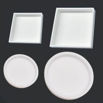
We manufacture high-quality PTFE components—including seals, liners, and custom labware—for the semiconductor, medical, laboratory, and industrial sectors. Whether you require prototypes or high-volume production, our expertise ensures your parts meet exact specifications with superior dimensional stability.
Let us put our precision production and custom fabrication expertise to work for you. Contact KINTEK today to discuss your project requirements!
Visual Guide
Related Products
- Custom PTFE Filtration System Acid Resistant High Purity Semiconductor Grade Chemical Processing Filter
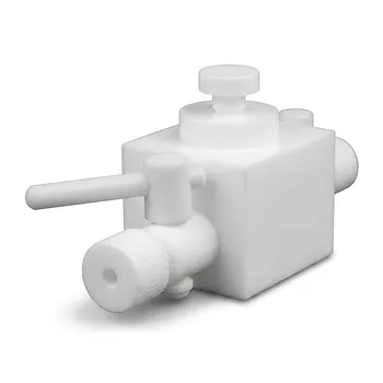
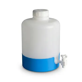
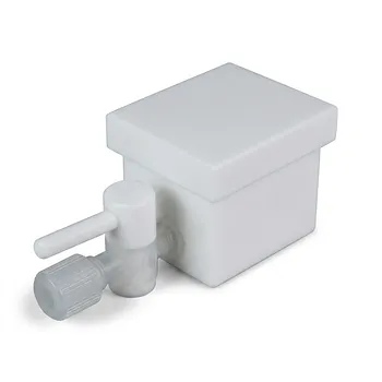
- High Corrosion Resistant PTFE Faucet Polytetrafluoroethylene Valve for Chemical Storage Drums and Fluid Transfer Systems Customizable Industrial Grade
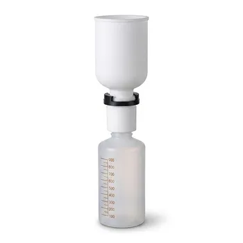
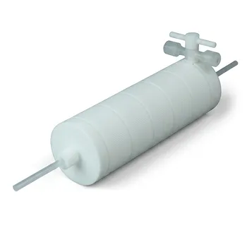
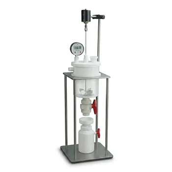
- PTFE PFA Vacuum Filtration System Corrosion Resistant Customizable Shatterproof Laboratory Device
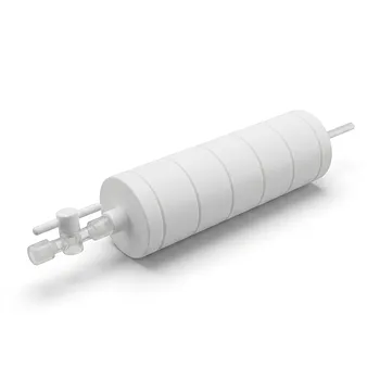
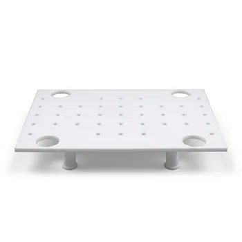
- PTFE Corrosion Resistant Filter with PFA Valve Connections and Integrated Sieve Plate
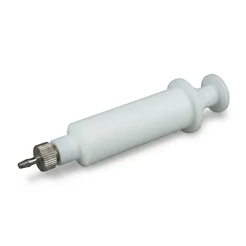
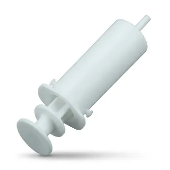
- High Temperature Chemical Resistant 50ml PTFE Syringe Customized Teflon Injector with Threaded Seal for Trace Analysis
People Also Ask
- Why are Polytetrafluoroethylene (PTFE) filters preferred for pharmaceutical and laboratory bioprocessing applications?
- How does the hydrophobicity of PTFE filters benefit their use? Ensure Uninterrupted Gas Flow and Solvent Filtration
- Which chemicals are fully compatible with PTFE filters? Discover Unmatched Chemical Resistance
- What sizes and pore options are available for PTFE filters? Choose the Right Filter for Your Application
- What are common industrial applications of PTFE filters? Master Critical Filtration in Demanding Industries