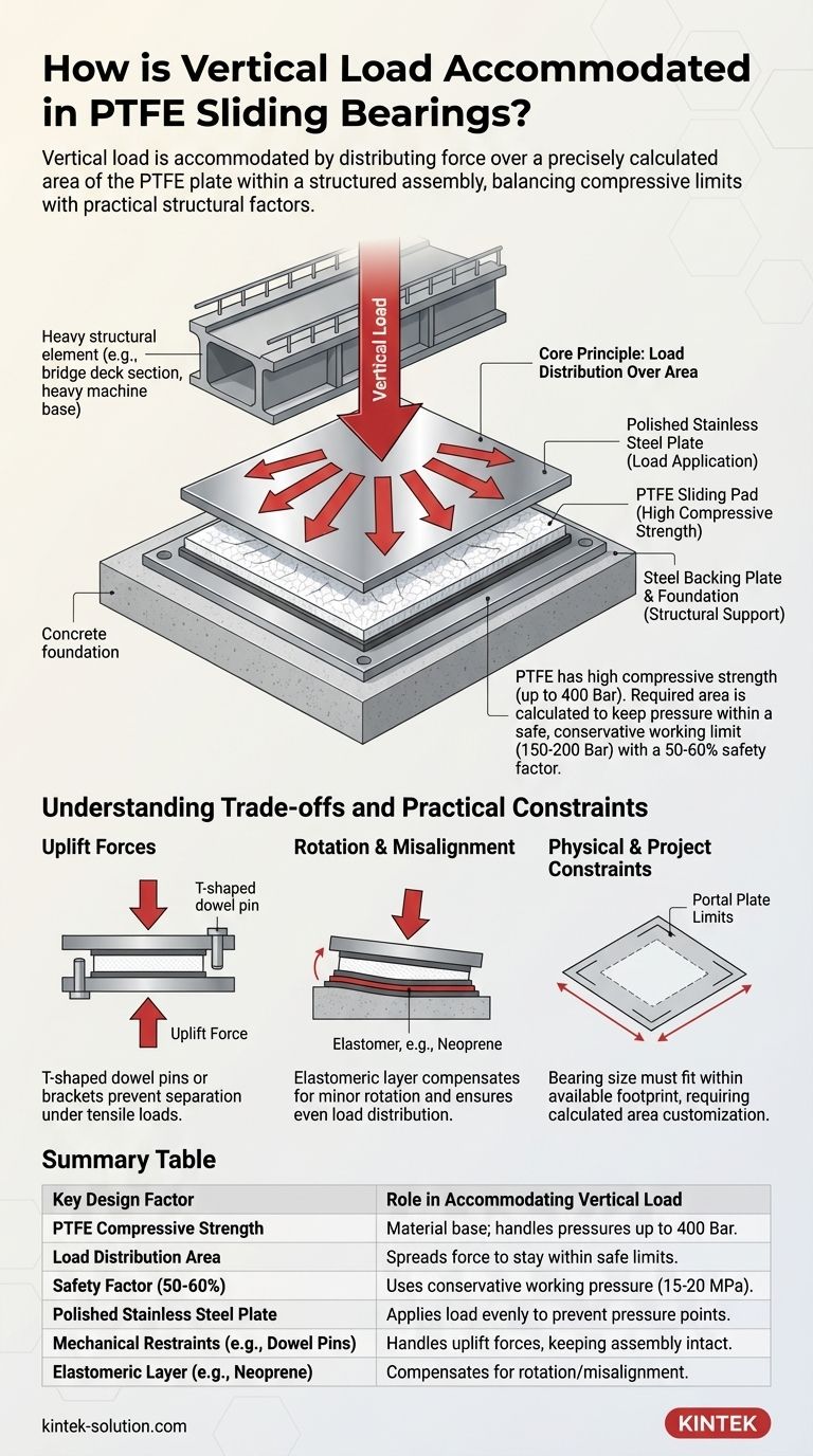
In short, vertical load in a PTFE sliding bearing is accommodated by distributing the force over a precisely calculated area of the PTFE plate. This design leverages PTFE's high compressive strength within a structural assembly, where a polished stainless steel plate applies the load evenly, allowing the bearing to support immense weight while still permitting horizontal movement.
The key to handling vertical load is not the PTFE material in isolation, but the entire bearing assembly. The design must balance the PTFE's compressive limits with practical factors like structural rotation and potential uplift forces to create a system that is both strong and functional.
The Core Principle: Load Distribution Over Area
The fundamental design of a PTFE bearing is based on the relationship between force, pressure, and area. The vertical load is a known force, and the PTFE material has a known pressure limit.
The Role of Compressive Strength
Polytetrafluoroethylene (PTFE) is a material with very high compressive strength. It can theoretically handle contact pressures up to 400 Bar (40 MPa).
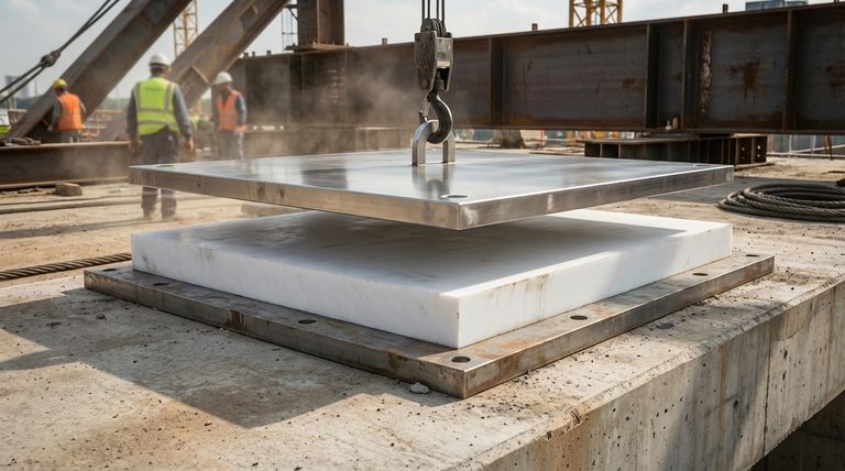
This inherent strength is what allows a relatively small pad of PTFE to support massive structural elements like bridge decks or heavy industrial equipment.
Calculating the Required PTFE Area
The engineering process begins with the specified vertical load. The required surface area of the PTFE pad is then calculated to ensure the pressure on it remains within safe limits.
For example, if a bearing must support a load that creates 200 tons of force, the designer calculates the square centimeters of PTFE needed to keep the pressure well below the material's failure point.
The Importance of Safety Factors
While PTFE can handle 400 Bar, professional designs never approach this limit. A crucial safety factor of 50-60% is applied.
This means that for design and calculation purposes, the maximum allowable pressure is typically limited to 150-200 Bar. This conservative approach accounts for unforeseen stresses and ensures long-term durability.
Anatomy of a Load-Bearing Assembly
A PTFE sliding bearing is more than just a piece of plastic. It is a carefully constructed assembly designed to manage multiple forces simultaneously.
The Key Components
The typical assembly consists of two main halves. One side features a steel backing plate with a sheet of PTFE permanently bonded to it.
The other half consists of a highly polished stainless steel plate, also welded to a steel backing plate. The vertical load from the structure is applied through this stainless steel plate directly onto the PTFE surface.
How the Load is Transferred
The rigid steel plates are critical. They ensure that the vertical load is transferred uniformly across the entire surface of the PTFE pad.
This prevents pressure points and "edge loading," which could damage the PTFE. The smooth interface between the polished stainless steel and the PTFE is what allows for a low-friction sliding motion even while under immense vertical pressure.
Understanding the Trade-offs and Practical Constraints
Accommodating vertical load in the real world involves more than simple compression. The design must account for other forces and physical limitations.
The Challenge of Uplift Forces
Structures can be subjected to uplift loads from factors like heavy winds. This creates a tensile or pulling force on the bearing, trying to separate the two halves.
To counter this, bearings are often designed with T-shaped dowel pins or brackets. These mechanical restraints lock the two plates together, allowing them to handle uplift without dislodging or misaligning.
Accommodating Rotation and Misalignment
Structural loads are rarely perfectly perpendicular. Minor rotation or misalignment can cause the load to concentrate on one edge of the bearing, leading to failure.
To solve this, a thin layer of an elastomer, like neoprene, is often incorporated into the assembly. This flexible layer can deform slightly, compensating for minor rotation and ensuring the vertical load remains evenly distributed across the PTFE.
Physical and Project Constraints
The final design is often dictated by the project's physical realities. The available space on a concrete pier or steel beam (the "portal plate") limits the maximum size of the bearing.
This constraint means designers must work backward, ensuring the calculated PTFE area can fit within the allowed footprint, which can sometimes require creative or customized solutions.
Making the Right Choice for Your Goal
To ensure a successful design, your approach must align with the specific demands of your project.
- If your primary focus is pure vertical compression: Concentrate on calculating the correct PTFE surface area using a conservative working pressure (150-200 Bar) to guarantee a high safety margin.
- If your project involves potential uplift forces: You must specify mechanical restraints like T-shaped dowel pins or integrated brackets to handle tensile loads and prevent separation.
- If you anticipate slight rotation or structural misalignment: Incorporate an elastomeric layer (like neoprene) into the bearing assembly to ensure even load distribution and prevent premature wear.
By understanding these principles, you can confidently specify a PTFE bearing system that is robust, reliable, and perfectly suited to its structural task.
Summary Table:
| Key Design Factor | Role in Accommodating Vertical Load |
|---|---|
| PTFE Compressive Strength | Material base; handles pressures up to 40 MPa (400 Bar). |
| Load Distribution Area | Calculated PTFE surface area spreads force to stay within safe limits. |
| Safety Factor (50-60%) | Design uses a conservative working pressure of 15-20 MPa for durability. |
| Polished Stainless Steel Plate | Applies load evenly across the PTFE surface to prevent pressure points. |
| Mechanical Restraints (e.g., Dowel Pins) | Handles uplift forces to keep the assembly intact under tension. |
| Elastomeric Layer (e.g., Neoprene) | Compensates for rotation/misalignment to maintain even load distribution. |
Need a PTFE Bearing Solution for Your High-Load Application?
Specifying the right PTFE sliding bearing is critical for the safety and longevity of structures in the semiconductor, medical, laboratory, and industrial sectors. KINTEK specializes in the precision manufacturing of PTFE components, including custom bearing assemblies.
We partner with you from prototype to high-volume production, ensuring your design meets exact load, movement, and durability requirements.
Contact KINTEK today to discuss your project's specifications and leverage our expertise in high-performance PTFE fabrication.
Visual Guide
Related Products
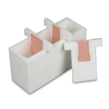
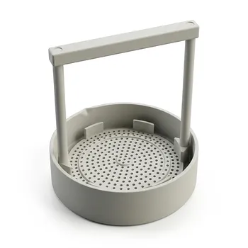
- White PTFE Electrolytic Cell with Movable Slider and Insulated Lid for Fluorine Corrosion Resistance
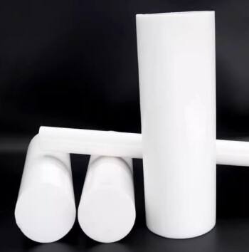
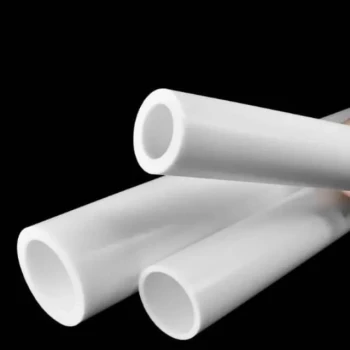
- Customizable PTFE Rods for Advanced Industrial Applications
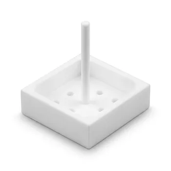
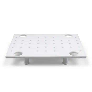
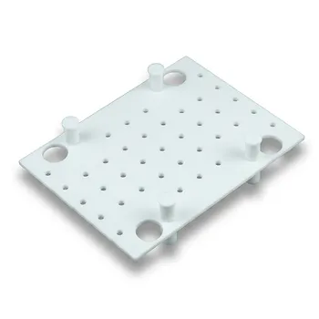
- PTFE Silicon Wafer Holder for Acid Etching and Cleaning Process 2 4 6 8 Inch Customizable High Temperature Resistant
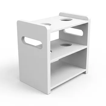
- Custom PTFE Acid Resistant Support Rack for PFA Hydrogen Absorption Systems Multi Hole Configurations
- Custom Graphite Filled PTFE Rods for Advanced Industrial Applications
People Also Ask
- How does the hydrophobicity of PTFE benefit electrochemical measurements? Enhance Stability and Precision in Your Lab
- How does ion migration occur within an electrolytic cell during electrolysis? Master Charge Transport Mechanisms
- What are the advantages of using electrolytic cells for refining non-ferrous metals like copper and zinc? 99.99% Purity
- What is the fundamental operating principle of an electrolytic cell? Master Energy-Driven Redox Reactions
- How are electrolytic cells utilized in the Hall-Héroult process? Optimizing Purity and Energy Efficiency