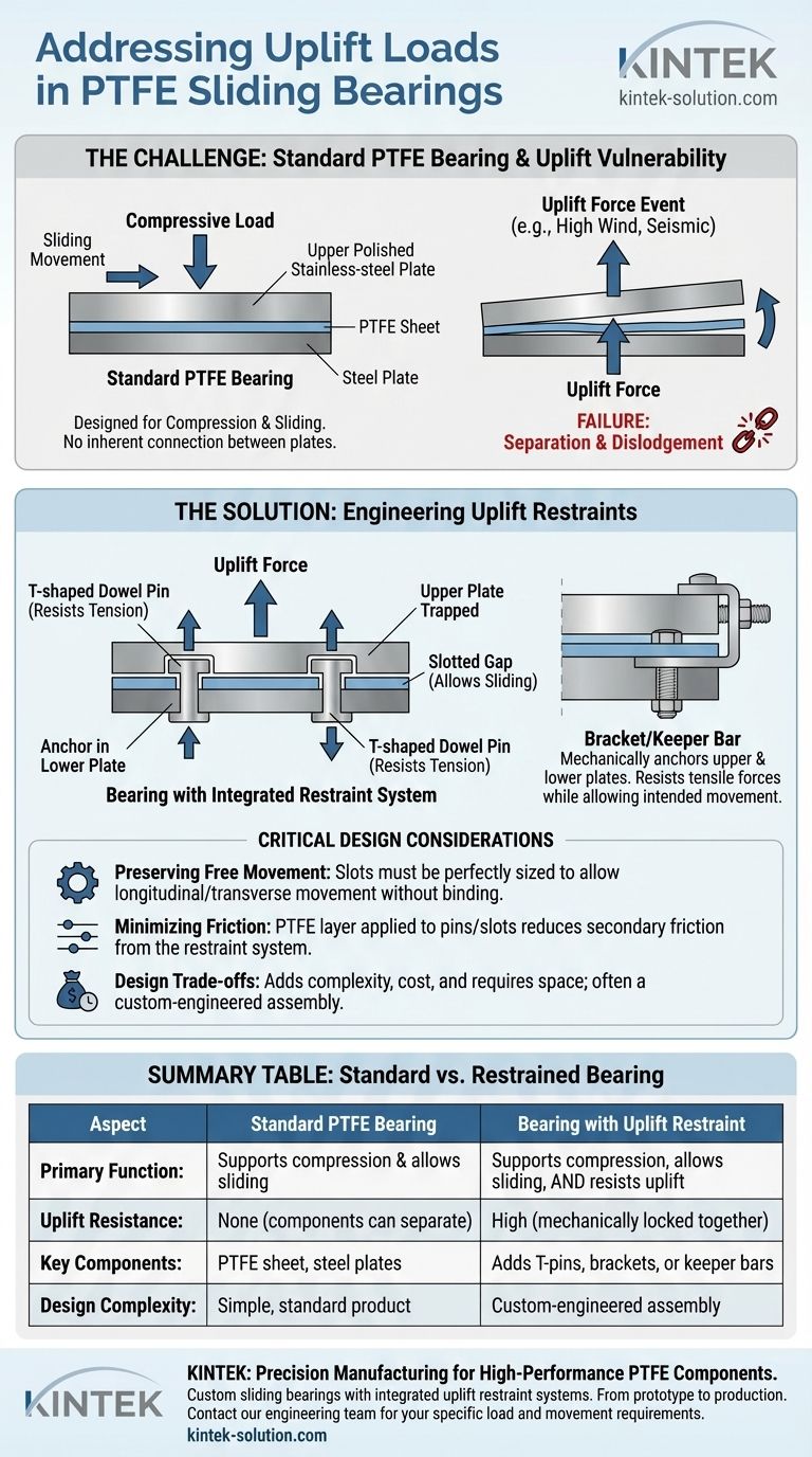
To address uplift loads, PTFE sliding bearings are mechanically anchored using external restraints like T-shaped dowel pins or brackets. Since the core bearing is designed only for compression and sliding, these added components physically lock the upper and lower plates together to resist tensile forces, preventing misalignment or dislodging from events like heavy winds.
A standard PTFE sliding bearing has no inherent ability to resist uplift forces. The solution is not within the bearing itself, but in adding a separate, engineered restraint system that mechanically holds the bearing assembly together while still allowing for the intended sliding movement.
The Bearing's Primary Function and Vulnerability
Designed for Compression and Sliding
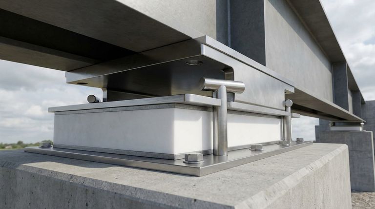
A PTFE sliding bearing is a simple but effective system. It consists of a PTFE sheet bonded to a lower steel plate and a polished stainless-steel plate welded to the superstructure above it.
The system's entire purpose is to support immense vertical (compressive) loads while allowing the stainless-steel plate to slide smoothly across the low-friction PTFE surface. This accommodates movement from factors like thermal expansion.
An Inherent Weakness to Uplift
By design, the top and bottom components of the bearing are not connected. They are held together only by the constant downward force of the structure they support.
If an uplift force—caused by wind, seismic activity, or mechanical dynamics—exceeds the compressive load, nothing prevents the upper and lower plates from separating. This can lead to catastrophic dislodgement and failure.
Engineering Restraints for Uplift Forces
T-Shaped Dowel Pins
The most common solution is the integration of T-shaped dowel pins. The stem of the "T" is fixed to one plate, while the head engages with a slot in the opposing plate.
This design mechanically locks the two plates together. If an uplift force occurs, the head of the pin pulls against the slot, preventing separation. These pins must handle significant tensile loads and are often made from high-strength stainless steel.
Brackets and Keepers
In other applications, brackets or keeper bars can be bolted or welded alongside the bearing. These components create a physical overhang that traps the opposing bearing plate, serving the same function as a T-pin system.
Preserving Free Movement is Critical
The key design challenge is restraining uplift without impeding the bearing's primary sliding function.
The slots that accept the dowel pins must be sized with specific gaps to allow for the expected longitudinal or transverse movement. The engineering must perfectly balance restraint with freedom.
Minimizing Friction in the Restraint System
To ensure the restraint mechanism doesn't interfere with smooth sliding, a layer of PTFE can be applied between the steel pin and its corresponding slot. This minimizes any secondary friction created by the uplift system itself.
Understanding the Design Trade-offs
Added Complexity and Cost
A standard bearing is a straightforward component. Incorporating an uplift restraint system transforms it into a custom-engineered assembly. This adds complexity to the design, manufacturing, and installation, which in turn increases the cost.
Space and Installation Constraints
Uplift restraints require physical space. On a crowded portal plate or in a tightly designed connection, finding room for robust pins or brackets can be a major challenge.
Furthermore, project constraints may restrict on-site welding or bolting, requiring more complex and expensive pre-fabricated solutions.
The Impact of Late-Stage Design
Bearings are often considered late in the design process. When an uplift requirement is discovered at this stage, it forces a custom solution with minimal lead time, often categorizing the bearing as a premium, project-specific product.
Making the Right Choice for Your Design
Successfully implementing a PTFE bearing in an environment with uplift potential requires careful planning. Your primary goal will dictate your design priorities.
- If your primary focus is resisting high wind or seismic uplift: The tensile strength of the restraint material (e.g., stainless steel pins) and the integrity of its connection are your most critical specifications.
- If your primary focus is accommodating large thermal movements: You must precisely define the dimensions of the pin slots and gaps to prevent the restraint system from binding as the structure expands and contracts.
- If your primary focus is controlling project costs and schedule: Address all load conditions, including uplift, during the initial engineering phase to specify the correct bearing solution from the start.
By engineering a dedicated restraint system, you ensure the bearing assembly remains secure, allowing it to perform its essential function of supporting loads while permitting movement.
Summary Table:
| Aspect | Standard PTFE Bearing | Bearing with Uplift Restraint |
|---|---|---|
| Primary Function | Supports compression & allows sliding | Supports compression, allows sliding, AND resists uplift |
| Uplift Resistance | None (components can separate) | High (mechanically locked together) |
| Key Components | PTFE sheet, steel plates | Adds T-pins, brackets, or keeper bars |
| Design Complexity | Simple, standard product | Custom-engineered assembly |
Need a custom PTFE bearing solution for your project's specific uplift and movement requirements?
KINTEK specializes in the precision manufacturing of high-performance PTFE components, including custom sliding bearings with integrated uplift restraint systems for the semiconductor, medical, laboratory, and industrial sectors. We handle everything from initial prototypes to high-volume production, ensuring your design is secure, functional, and cost-effective.
Contact our engineering team today to discuss your project's load and movement specifications.
Visual Guide
Related Products
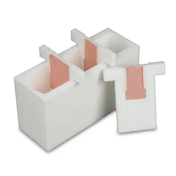
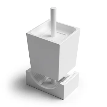
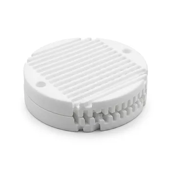
- White PTFE Electrolytic Cell with Movable Slider and Insulated Lid for Fluorine Corrosion Resistance
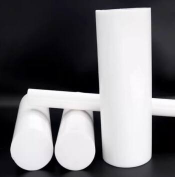
- Customizable PTFE Rods for Advanced Industrial Applications
- Custom Graphite Filled PTFE Rods for Advanced Industrial Applications
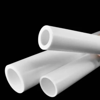
- Custom PTFE Sleeves and Hollow Rods for Advanced Applications
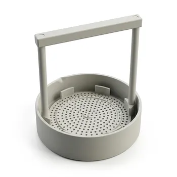
- Custom PTFE Acid Resistant Support Rack for PFA Hydrogen Absorption Systems Multi Hole Configurations
People Also Ask
- What are the primary components required for the construction of a standard electrolytic cell? Essential Hardware Guide
- What is the fundamental operating principle of an electrolytic cell? Master Energy-Driven Redox Reactions
- How does ion migration occur within an electrolytic cell during electrolysis? Master Charge Transport Mechanisms
- How is current efficiency calculated in the context of an electrolytic cell? Formula and Optimization Guide
- How does the hydrophobicity of PTFE benefit electrochemical measurements? Enhance Stability and Precision in Your Lab