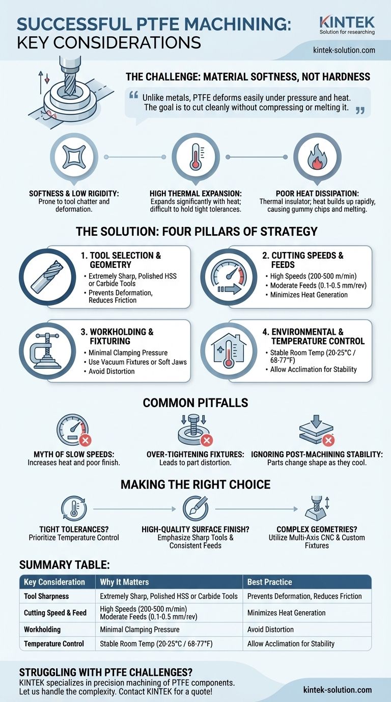
To machine PTFE successfully, you must adapt your strategy to its unique properties. Success hinges on using extremely sharp tools, low and consistent cutting speeds, minimal clamping pressure, and strict temperature control to counteract the material's inherent softness and high rate of thermal expansion.
The core challenge of machining Polytetrafluoroethylene (PTFE) is not its hardness, but its softness. Unlike metals, PTFE deforms easily under pressure and heat, meaning traditional machining techniques will lead to dimensional inaccuracies and poor finishes. The goal is to cut the material cleanly without compressing or melting it.
The "Why": Understanding PTFE's Unique Machining Challenges
PTFE, often known by the brand name Teflon, behaves very differently from metals and even other plastics. Its properties are what make it useful, but they also create specific obstacles during machining.
Softness and Low Rigidity
PTFE is an exceptionally soft material. This softness means it can easily be pushed away by a cutting tool rather than being cleanly sheared.
This can lead to tool chatter, where the tool bounces off the material, resulting in a poor surface finish. It also makes the material prone to deformation under clamping or cutting pressure.
High Coefficient of Thermal Expansion
PTFE expands and contracts significantly with changes in temperature. Even the heat generated from the friction of a cutting tool is enough to cause the part to grow.
This makes holding tight tolerances extremely difficult. A part measured as accurate while warm from machining may become out of tolerance once it cools to room temperature.
Poor Heat Dissipation
The material is a thermal insulator, meaning it doesn't conduct heat away from the cutting zone effectively.
This trapped heat can build up rapidly, causing the PTFE to exceed its low melting point. This results in gummy chips, a poor surface finish, and can even create thermal stress within the component.
The "How": Key Pillars of a Successful PTFE Strategy
Adapting your process to these challenges requires a deliberate approach focused on four key areas.
Pillar 1: Tool Selection and Geometry
The single most important factor is the sharpness of your cutting tool. A dull tool will deform PTFE long before it cuts it.
Use High-Speed Steel (HSS) or carbide tools that are ground to a razor-sharp edge. Polished and uncoated surfaces are often preferred as they reduce friction and material buildup.
Pillar 2: Cutting Speeds and Feeds
Your goal is to minimize heat generation. This requires a careful balance of speed and feed rate.
Use relatively high cutting speeds (200–500 m/min) combined with a moderate feed rate (0.1–0.5 mm/rev). This allows the tool to shear the material quickly before significant heat can build up in one spot. Coolants can also be used to manage temperature for critical dimensions.
Pillar 3: Workholding and Fixturing
Improper clamping is a primary source of failure. Overtightening a vise or fixture will easily compress and distort a PTFE workpiece.
Use minimal clamping pressure. Whenever possible, use fixtures that support a large surface area of the part, such as vacuum fixtures or soft jaws. For thin-walled parts, providing internal support is critical to prevent collapse during machining.
Pillar 4: Environmental and Temperature Control
Because of its high thermal expansion, the temperature of the material and the environment is critical for precision work.
Maintain a stable room temperature between 20–25°C (68–77°F). Allowing the material to acclimate to this temperature before and after machining ensures dimensional stability and accuracy.
Understanding the Trade-offs and Common Pitfalls
Avoiding common mistakes is as important as following the best practices. Many machinists new to PTFE apply techniques from other materials that prove counterproductive.
The Myth of Slow Speeds
While low feed rates are important, running the tool's rotational speed too slowly can be a mistake. Insufficient surface speed can increase tool pressure and rubbing, generating more heat and leading to a poor finish.
Over-tightening Fixtures
The most common error is treating PTFE like a rigid metal. The instinct to clamp a part tightly for security will invariably lead to deformation, resulting in parts that are out of tolerance as soon as they are released from the fixture.
Ignoring Post-Machining Stability
A part that measures perfectly right off the machine can be a failure. You must account for the material's tendency to change shape as it cools. Allow parts to stabilize at room temperature before conducting a final inspection.
Making the Right Choice for Your Goal
Your specific objective will determine which considerations are most critical.
- If your primary focus is tight dimensional tolerance: Prioritize stable temperature control and allow the material to acclimate before final cuts and inspection.
- If your primary focus is a high-quality surface finish: Emphasize using exceptionally sharp, polished tools and maintaining a consistent feed rate to avoid chatter.
- If your primary focus is machining complex geometries: Utilize multi-axis CNC machines and custom support fixtures, such as vacuum chucks, to ensure workpiece stability without distortion.
Ultimately, successful PTFE machining is achieved by respecting the material's unique character rather than fighting it.
Summary Table:
| Key Consideration | Why It Matters | Best Practice |
|---|---|---|
| Tool Sharpness | Prevents deformation and ensures a clean cut | Use razor-sharp, polished HSS or carbide tools |
| Cutting Speed & Feed | Minimizes heat buildup and material gumming | High speed (200-500 m/min), moderate feed (0.1-0.5 mm/rev) |
| Workholding | Avoids part distortion under pressure | Use minimal clamping force; prefer vacuum fixtures or soft jaws |
| Temperature Control | Counters high thermal expansion for tight tolerances | Maintain stable room temperature (20-25°C); allow part acclimation |
Struggling with PTFE's unique machining challenges? KINTEK specializes in precision machining of PTFE components like seals, liners, and custom labware. Our expertise in managing softness and thermal expansion ensures your parts meet the tightest tolerances and highest quality standards, from prototype to high-volume production.
Let us handle the complexity. Contact KINTEB today for a quote on your PTFE project!
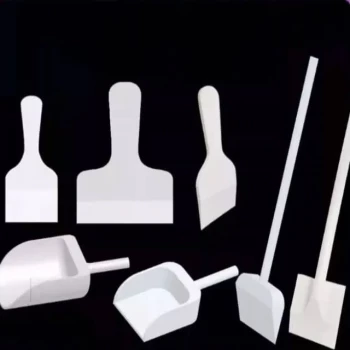
Visual Guide
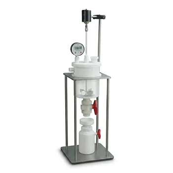
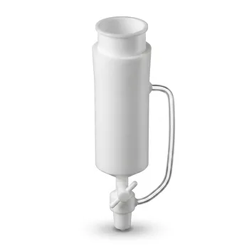
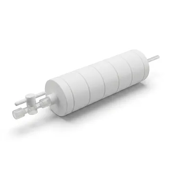
Related Products
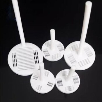
- Custom Machined Molded PTFE Teflon Parts Manufacturer for Laboratory ITO FTO Conductive Glass Cleaning Flower Basket
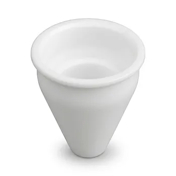
- Custom Machined PTFE Conical Sample Cell Corrosion Resistant Triangular Fluoropolymer Container for Trace Analysis
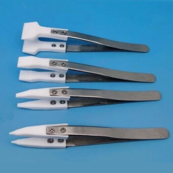
- Custom PTFE Parts Manufacturer for Teflon Parts and PTFE Tweezers
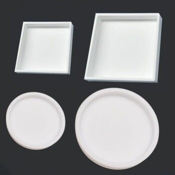
- Custom PTFE Parts Manufacturer for Teflon Containers and Components
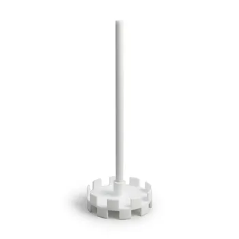
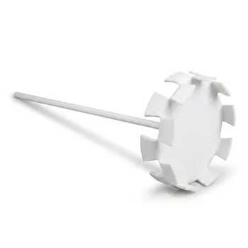
- Corrosion Resistant PTFE Stirring Impeller and Customizable Polytetrafluoroethylene Dispersion Disk
People Also Ask
- How does the structural design of a PTFE flower basket ensure uniform fluid access to substrates? Optimize Lab Yields
- What is the operating temperature range for PTFE flower baskets? Thermal limits and performance from -200°C to +260°C.
- What are the primary functions and design features of a PTFE flower basket? Optimize High-Purity Chemical Processing
- How do PTFE flower baskets compare to quartz or stainless-steel carriers? Maximize ROI with Low TCO Solutions
- How do PTFE flower baskets contribute to purity in semiconductor manufacturing? Achieve Sub-10 ppt Purity & Zero Leaching