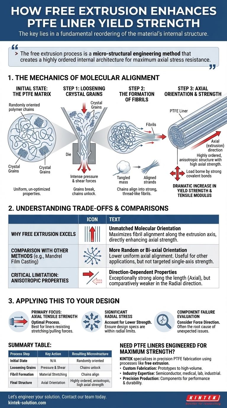
The key to enhanced yield strength in free-extruded PTFE liners lies in a fundamental reordering of the material's internal structure. The process transforms a random matrix of polymer chains into a highly organized, axially aligned structure. This molecular alignment, achieved through the formation of fibrils, is what directly reinforces the material against forces applied along the length of the liner.
The free extrusion process is not merely a shaping technique; it is a micro-structural engineering method. It enhances yield strength by creating a highly ordered internal architecture where molecular chains are aligned for maximum resistance to axial stress.
The Mechanics of Molecular Alignment
To understand the increase in strength, we must look at what happens to the PTFE at a microscopic level during free extrusion. The process can be broken down into distinct stages that build upon one another.
The Initial State: The PTFE Matrix
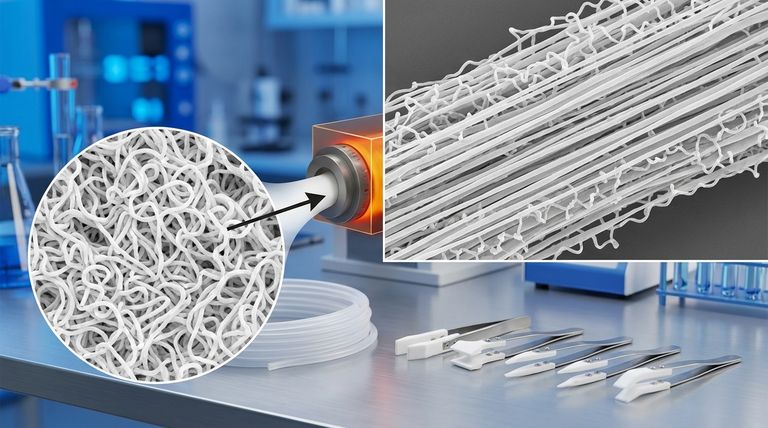
Before extrusion, PTFE material consists of long molecular chains. These chains are partially arranged into dense, folded structures known as crystal grains, which are embedded within a less-ordered, amorphous matrix. In this state, the chains are randomly oriented, giving the material uniform but un-optimized properties in all directions.
Step 1: Loosening the Crystal Grains
As the PTFE is forced through the extrusion die, intense pressure and shear forces are applied. This energy input effectively loosens and begins to break apart the tightly packed crystal grains. This step is critical, as it "unlocks" the folded molecular chains, making them available for reorientation.
Step 2: The Formation of Fibrils
With the crystal structure disrupted, the flowing material begins to stretch. The individual PTFE molecular chains are pulled from their folded state and align with the direction of flow. This process creates fibrils—extremely fine, thread-like structures composed of highly oriented polymer chains.
Think of this like pulling apart a cotton ball. Initially, the fibers are a tangled, random mass. As you pull it, the fibers begin to align in the direction you are pulling, forming a stronger, more coherent strand.
Step 3: Axial Orientation and Strength
The fibrils all form parallel to the axial (extrusion) direction. This creates a highly ordered, quasi-crystalline structure throughout the liner.
When a tensile force is applied along the liner's axis, the load is now borne by the strong covalent bonds along the backbones of these aligned molecular chains. This is far more effective than pulling on a random network, where the force would simply unravel the tangled chains. The result is a dramatic increase in the material's yield strength and tensile modulus along that specific axis.
Understanding the Trade-offs and Comparisons
No single manufacturing process is universally superior; each involves trade-offs. The choice of free extrusion is a deliberate one made to optimize for a specific type of performance.
Why Free Extrusion Excels
The primary advantage of free extrusion for PTFE liners is its unmatched ability to produce a high degree of molecular orientation. Compared to other methods, it maximizes the alignment of fibrils along the extrusion axis, which is directly responsible for the enhanced axial strength.
Comparison with Other Methods
Methods like mandrel extrusion or film casting do not achieve the same level of uniform axial orientation. The forces involved are different, often resulting in a more random or bi-axial (two-direction) orientation. While useful for other applications, these methods do not produce the targeted, single-axis strength enhancement that free extrusion does.
The Critical Limitation: Anisotropic Properties
This targeted strengthening comes at a cost: the material becomes anisotropic. This means its properties are direction-dependent.
While the liner becomes exceptionally strong along its length (axial direction), it will be comparatively weaker in the radial direction (perpendicular to the length). Any force trying to split the liner wall will be met with much less resistance, as it acts between the fibrils rather than along them.
Applying This to Your Design
Understanding this principle allows you to specify or evaluate components with greater precision. Your decision should be guided by the primary stresses the component will face in its application.
- If your primary focus is axial tensile strength: Free extrusion is the optimal process for creating liners that must resist stretching or pulling forces along their length.
- If your application involves significant radial stress: You must account for the lower strength in this direction and ensure your design specifications are within the material's limits.
- If you are evaluating a component failure: Always consider the direction of the applied force relative to the extrusion direction, as this is often the root cause of unexpected performance issues.
By understanding the link between the manufacturing process and molecular structure, you can ensure your components are precisely engineered for their intended function.
Summary Table:
| Process Step | Key Action | Resulting Microstructure |
|---|---|---|
| Initial State | N/A | Randomly oriented polymer chains in a matrix |
| Loosening Grains | Pressure & shear in the die | Crystal grains break apart, chains unlock |
| Fibril Formation | Material stretching | Chains align into strong, thread-like fibrils |
| Final Structure | Axial orientation | Highly ordered, anisotropic structure with high axial strength |
Need PTFE Liners Engineered for Maximum Strength?
At KINTEK, we specialize in precision PTFE fabrication, leveraging processes like free extrusion to deliver components with superior mechanical properties. Our expertise ensures your liners, seals, and labware are perfectly matched to your application's stress requirements.
We provide:
- Custom Fabrication: From prototypes to high-volume orders.
- Industry Expertise: Serving semiconductor, medical, laboratory, and industrial sectors.
- Precision Production: Components built for performance and durability.
Let's engineer your solution. Contact our team today to discuss your project requirements.
Visual Guide
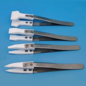
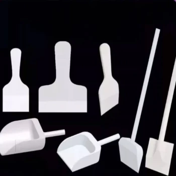
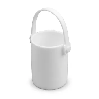
Related Products
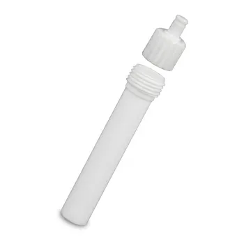
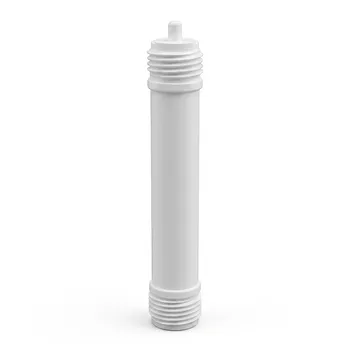
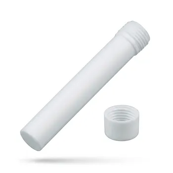
- High Purity PTFE Microwave Digestion Vessel Replacement Liner for Acid Sample Preparation and Trace Analysis
- High Purity PTFE Microwave Digestion Vessel for Soil and Food Analysis Acid Resistant Fluoropolymer Sample Preparation Liners
- High Purity TFM Microwave Digestion Vessels PTFE Acid Evaporation Liners Domestic GT-400 Equivalent Laboratory Reaction Containers
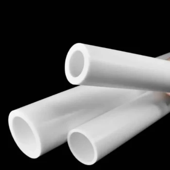
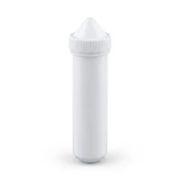
- Custom PTFE Sleeves and Hollow Rods for Advanced Applications
- High Temperature Chemical Resistant 50ml PTFE Syringe Customized Teflon Injector with Threaded Seal for Trace Analysis
People Also Ask
- What are the temperature and pressure capabilities of microwave digestion vessels? Maximize Lab Sample Prep Efficiency
- What are the advantages of using microwave digestion vessels for environmental analysis? Boost speed and sample accuracy.
- How does the closed-vessel design of microwave digestion vessels improve sample preparation? Unlock Superior Trace Analysis
- How does the dielectric property of PTFE benefit microwave-assisted digestion? Unlock Rapid and Uniform Sample Heating
- What are the operational efficiencies gained by using microwave digestion vessels? Boost Throughput and Precision