Properly installing a PTFE lined butterfly valve is achieved by carefully clamping the valve body between two pipe flanges using full-threaded stud bolts. The process relies on a precise, sequential tightening pattern to create an even clamping force, which compresses the PTFE seat to form a reliable, leak-free seal without damaging the liner.
The core challenge of installing a PTFE lined valve is not simply mechanical assembly; it is the precise application of clamping force. Overtightening can crush the PTFE seat, while uneven pressure leads to leaks, defeating the valve's primary purpose of providing a perfect seal in corrosive environments.
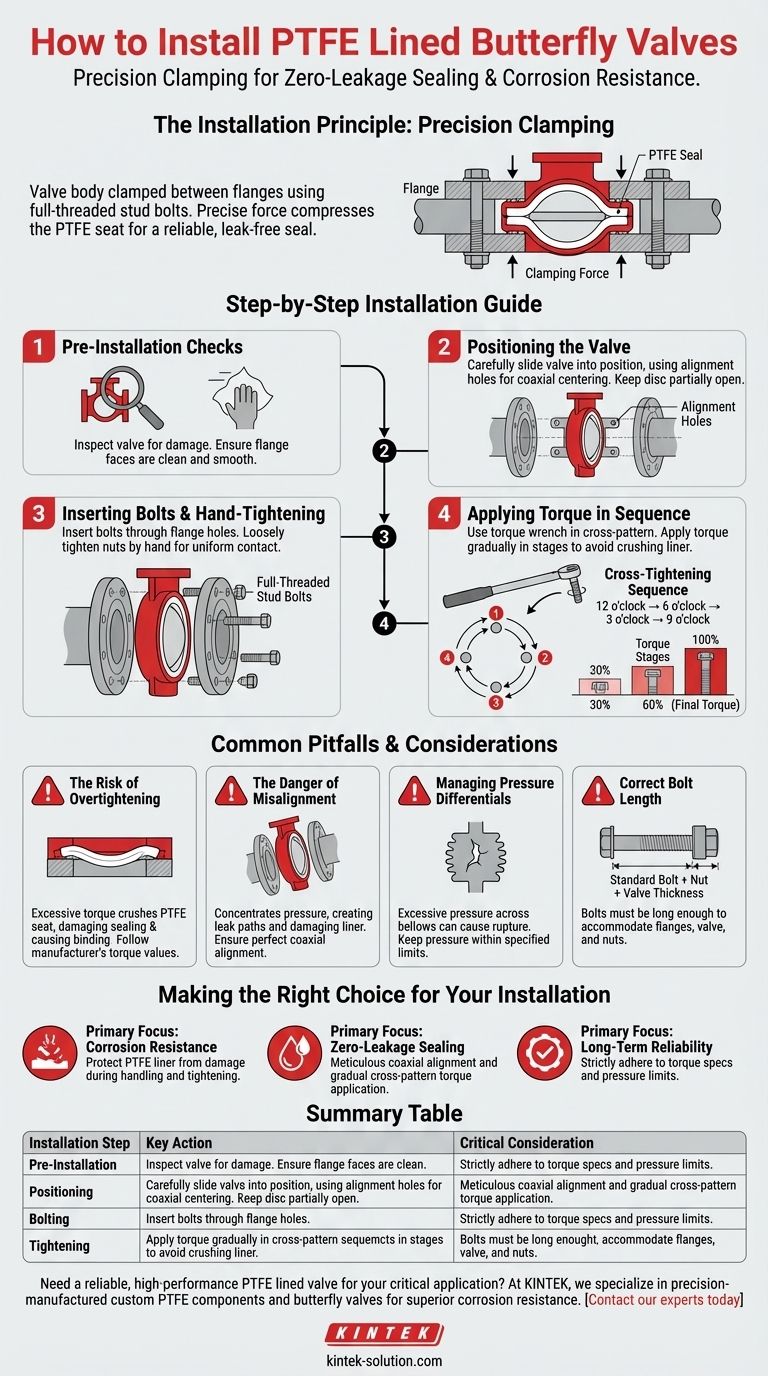
The Installation Principle: Precision Clamping
A PTFE lined butterfly valve is a "wafer" or "lug" style valve, meaning it has no flanges of its own. It is designed to be sandwiched directly between two existing pipe flanges.
Understanding the Sealing Mechanism
The seal is not created by a separate gasket. Instead, the PTFE liner extends over the faces of the valve body, acting as the primary sealing surface against the pipe flanges.
When the flanges are bolted together, they exert a clamping force that compresses this PTFE face, creating a highly effective and chemically resistant seal.
The Role of Alignment
The valve body typically has two or four positioning holes (lugs). These are not for bearing the load but are critical for ensuring the valve is perfectly centered and coaxially aligned with the pipe during installation.
Proper alignment guarantees that the clamping force is distributed evenly around the entire PTFE sealing face.
Step-by-Step Installation Guide
Following a methodical process is essential to protect the valve's integrity and ensure a zero-leakage seal.
Step 1: Pre-Installation Checks
Before you begin, inspect the valve for any damage to the PTFE liner or seat. Confirm that the pipe flange faces are clean, smooth, and free of any debris that could compromise the seal.
Step 2: Positioning the Valve
Carefully spread the flanges apart just enough to slide the valve into position. Use the alignment holes on the valve body to guide it into a centered position between the flanges.
Ensure the disc is in a partially open position so it does not extend beyond the valve body face, which could cause it to be damaged when the flanges are brought together.
Step 3: Inserting Bolts and Hand-Tightening
Insert the full-threaded stud bolts through the flange holes. Loosely tighten the nuts by hand until they are snug, ensuring the valve remains centered.
This initial step brings the flanges into uniform contact with the PTFE sealing faces without applying significant pressure.
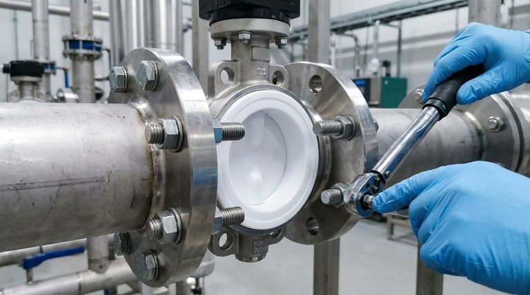
Step 4: Applying Torque in Sequence
Tighten the bolts using a torque wrench. It is critical to follow a cross-tightening sequence (e.g., 12 o'clock, 6 o'clock, 3 o'clock, 9 o'clock) to apply pressure evenly.
Apply the torque in gradual increments, typically in three stages: 30% of the final torque, then 60%, and finally 100%. This prevents the liner from being crushed or deformed in one area.
Common Pitfalls and Considerations
The unique properties of PTFE demand special attention to avoid common installation errors that can lead to valve failure.
The Risk of Overtightening
PTFE is a relatively soft material. Excessive torque will crush the PTFE seat and liner, permanently damaging the valve's sealing capability and potentially causing the disc to bind. Always adhere to the manufacturer's specified torque values.
The Danger of Misalignment
Even slight misalignment concentrates pressure on one side of the valve. This not only creates a potential leak path on the opposite side but also risks damaging the liner and disc at the point of highest pressure.
Managing Pressure Differentials
For PTFE lined valves sealed with bellows, excessive pressure differences across the valve can cause the delicate PTFE bellows to rupture. Ensure your system's operating pressure remains within the valve's specified allowable range.
Correct Bolt Length
The length of the stud bolts is critical. The bolt must be long enough to accommodate the thickness of both flanges, the valve body, washers, and two nuts, with a small margin. A common calculation is: Standard Bolt Length + Nut Length + Valve Thickness.
Making the Right Choice for Your Installation
Your primary goal will determine where to focus your attention during the installation process.
- If your primary focus is corrosion resistance: Your main priority is to protect the integrity of the PTFE liner from scratches or crushing during handling and tightening.
- If your primary focus is zero-leakage sealing: Meticulous attention to coaxial alignment and the gradual, cross-patterned application of torque is non-negotiable.
- If your primary focus is long-term reliability: Strictly adhere to the manufacturer's torque specifications and ensure system pressures do not exceed the valve's design limits.
Ultimately, a successful installation is one of precision, where careful procedure protects the valve's advanced materials and guarantees its performance.
Summary Table:
| Installation Step | Key Action | Critical Consideration |
|---|---|---|
| Pre-Installation | Inspect valve and clean flanges. | Ensure no damage to PTFE liner or seat. |
| Positioning | Center valve using alignment holes. | Keep disc partially open to avoid damage. |
| Bolting | Insert full-threaded stud bolts. | Use correct bolt length for the assembly. |
| Tightening | Follow a cross-tightening sequence with a torque wrench. | Apply torque in stages (30%, 60%, 100%) to avoid crushing the PTFE. |
Need a reliable, high-performance PTFE lined valve for your critical application?
Proper installation starts with a precision-manufactured valve. At KINTEK, we specialize in custom-fabricated PTFE components—including seals, liners, labware, and butterfly valves—for the semiconductor, medical, laboratory, and industrial sectors. Our focus on precision production ensures a perfect fit and superior corrosion resistance, whether you need prototypes or high-volume orders.
Let us provide the reliable foundation for your leak-free system. Contact our experts today to discuss your specific requirements!
Visual Guide
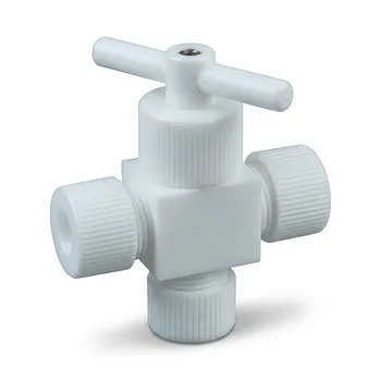
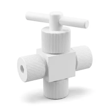
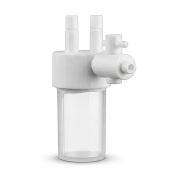
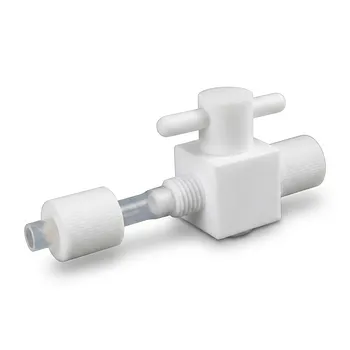
Related Products
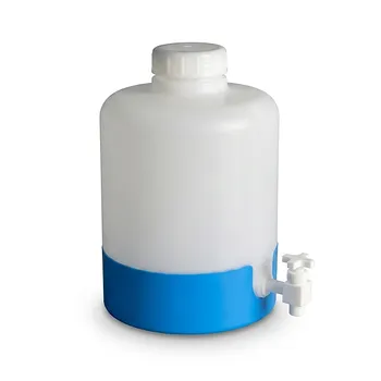
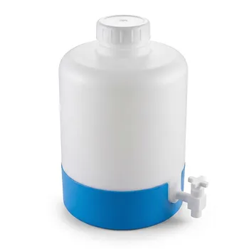
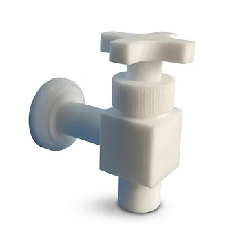
- High Corrosion Resistant PTFE Faucet Polytetrafluoroethylene Valve for Chemical Storage Drums and Fluid Transfer Systems Customizable Industrial Grade
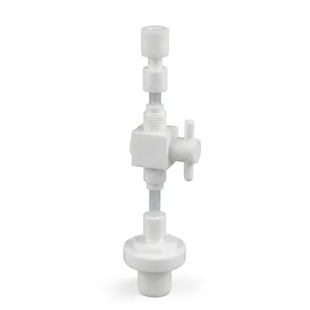
- High Purity PFA PTFE Flare Stop Valves Customizable 2-Way 3-Way Reducing Fluoropolymer Fluid Control Solutions
- High Purity PTFE Faucet Corrosion Resistant Polytetrafluoroethylene Drum Valve Customizable Lab Chemical Fluid Control
- Corrosion Resistant PTFE Polytetrafluoroethylene Valve and Customizable Laboratory Fluid Dispensing Faucet for Aggressive Chemical Handling in Industrial Storage Tanks and Plastic Drums
- Custom PTFE Valve 2-Way 3-Way Corrosion Resistant Low Background Virgin Fluoropolymer Industrial Fluid Control
People Also Ask
- What is the typical operating temperature and pressure range for PTFE valves? Key Specs for Optimal Performance
- How do PTFE valves and components support high-purity liquid transfer? Ensure Product Integrity with Inert Materials
- What support is available for selecting the right PTFE valve design and size? Get Expert Guidance for Your Application
- What are the benefits of using PTFE valves in the food processing industry? Ensure Safety, Purity, and Efficiency
- What factors influence the design variations of PTFE valves? Select the Perfect Valve for Your Application