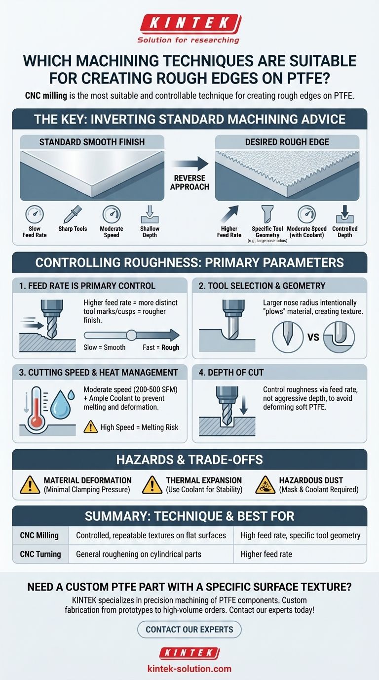
In short, CNC milling is the most suitable and controllable technique for creating rough edges on PTFE. While other methods like turning can also be used, milling offers superior flexibility for generating specific and repeatable surface textures by precisely manipulating tooling and cutting parameters.
The key to achieving a rough finish on PTFE is not about choosing a unique machining process, but about intentionally adjusting standard machining parameters—like feed rate and tool selection—to work against the typical goal of a smooth surface.
Why Standard Machining Advice Must Be Inverted
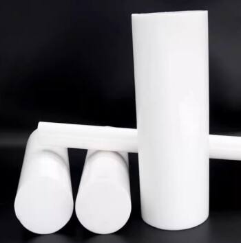
Polytetrafluoroethylene (PTFE) is a uniquely soft and thermally sensitive polymer. Most machining guides focus on overcoming these properties to achieve a smooth finish and tight tolerances.
To create a rough edge, you must deliberately leverage these properties by modifying the standard approach. This requires a careful balance, as aggressive techniques can easily lead to material deformation, melting, or poor dimensional accuracy.
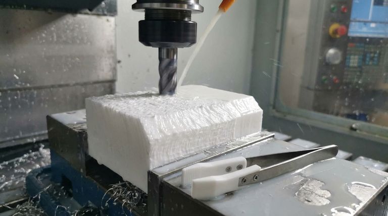
The Role of CNC Milling
CNC milling uses a rotating multi-point cutting tool to remove material from a stationary workpiece. This method is ideal for creating textures because you can control the tool's path with extreme precision across a surface. It allows you to create everything from a uniform rough finish to intricate, patterned textures.
The Role of CNC Turning
CNC turning is primarily used for cylindrical parts. A single-point tool moves along a rotating workpiece. While it can be used to create a rough finish (often seen as fine grooves), it is less versatile than milling for generating complex or non-uniform textures on flat edges.
Controlling Roughness: The Key Machining Parameters
Achieving a specific roughness is a function of how the cutting tool interacts with the material. The following parameters are your primary levers for control.
H3: Feed Rate is Your Primary Control
The feed rate—how quickly the workpiece moves relative to the cutting tool—has the most direct impact on surface roughness.
For a smooth finish, operators use a slow feed rate. To achieve a rougher finish, you should use a higher feed rate. This causes the tool to leave more distinct marks or "cusps" on the material surface with each pass.
H3: Tool Selection and Geometry Matter
Standard advice calls for extremely sharp tools, often made of High-Speed Steel (HSS) or carbide, to shear the material cleanly.
To increase roughness, consider using a tool with a specific geometry, such as a larger nose radius. This can intentionally "plow" through the material to a small degree, creating a more textured finish than a sharp, pointed tool.
H3: Cutting Speed and Heat Management
PTFE has a very high coefficient of thermal expansion and does not dissipate heat well. While high cutting speeds can contribute to a rougher finish, they also risk melting the material.
It is critical to operate within a moderate speed range (200 to 500 surface feet per minute) and use ample coolant to manage temperature. This prevents the surface from melting and ensures the roughness is due to mechanical cutting, not thermal damage.
H3: Depth of Cut
A shallow depth of cut is recommended for a smooth finish. While a deeper cut can induce more tool pressure and vibration, potentially increasing roughness, it also significantly increases the risk of deforming the soft PTFE. It is generally better to control roughness via feed rate rather than an aggressive depth of cut.
Understanding the Trade-offs and Hazards
Machining PTFE presents unique challenges that must be managed, especially when departing from standard procedures.
H3: Material Deformation
PTFE is soft and can be easily compressed. Minimal clamping pressure is essential. Over-tightening the workpiece in a vise will cause it to deform, leading to inaccurate dimensions once the part is released.
H3: Thermal Expansion
Because PTFE expands significantly with heat, any temperature increase during machining will cause the part to grow. This makes achieving tight tolerances difficult. Using coolant is not just for the finish; it is critical for dimensional stability.
H3: Hazardous Dust
Machining PTFE produces fine particle dust. This dust can be hazardous if inhaled. Always use a mask or ensure the work is performed under a steady stream of coolant to suppress dust creation.
Making the Right Choice for Your Goal
Your approach should be dictated by the type of roughness you need and the precision your application demands.
- If your primary focus is a controlled, repeatable texture: Use CNC milling and prioritize manipulating the feed rate while using a specific tool geometry and generous coolant.
- If your primary focus is general surface roughening for adhesion: A faster turning or milling operation with a higher feed rate may be sufficient, but always monitor for heat buildup.
- If your primary focus is safety and accuracy: Always use coolant to manage thermal expansion and suppress hazardous dust, and apply minimal clamping pressure to prevent deformation.
Ultimately, achieving the right rough finish on PTFE is a deliberate process of balancing these parameters to get the texture you need without compromising the part's integrity.
Summary Table:
| Technique | Best For | Key Parameter for Roughness |
|---|---|---|
| CNC Milling | Controlled, repeatable textures on flat surfaces | High feed rate, specific tool geometry |
| CNC Turning | General roughening on cylindrical parts | Higher feed rate |
Need a custom PTFE part with a specific surface texture?
At KINTEK, we specialize in precision machining of PTFE components like seals, liners, and labware. Our expertise in balancing parameters like feed rate and tool selection allows us to create the exact rough finish you require for applications in the semiconductor, medical, laboratory, and industrial sectors—all while ensuring dimensional accuracy and material integrity.
We offer custom fabrication from prototypes to high-volume orders. Contact our experts today to discuss your project and get a quote!
Visual Guide
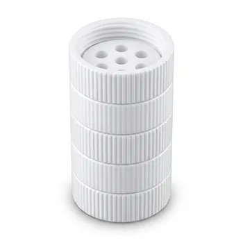
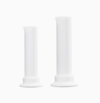
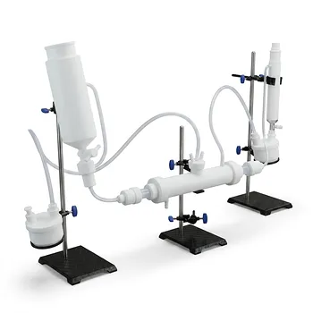
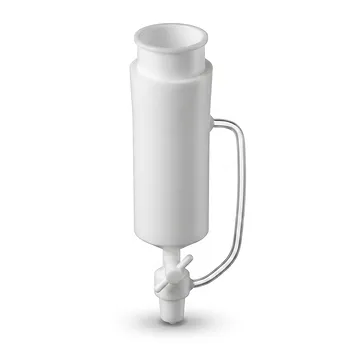
Related Products
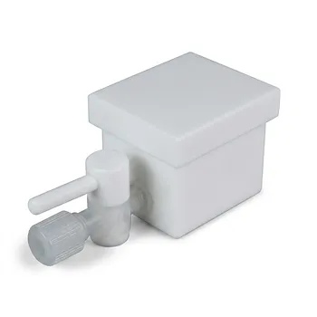
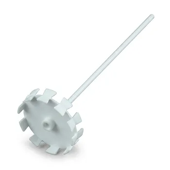
- Custom PTFE Laboratory Apparatus Corrosion Resistant Low Background Reaction Cells Precision CNC Fabrication
- Custom PTFE Ball Mill Grinding Jar 50ml Corrosion Resistant Low Background Lab Milling Vessel
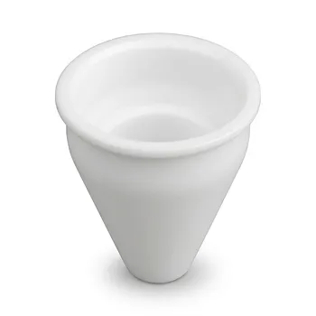
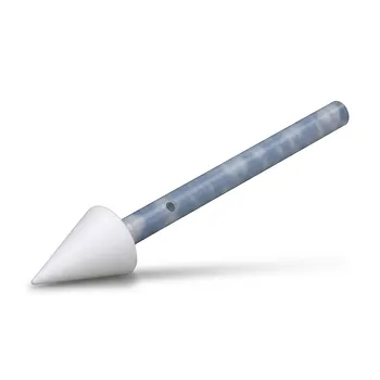
- Custom Machined PTFE Conical Sample Cell Corrosion Resistant Triangular Fluoropolymer Container for Trace Analysis
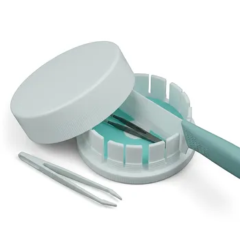
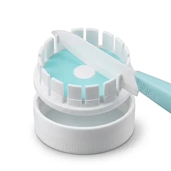
- High Purity PTFE Circular Filter Membrane Cutter with Ceramic Blade for Trace Analysis and CDC Laboratory Sample Preparation
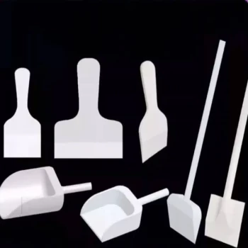
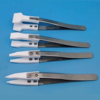
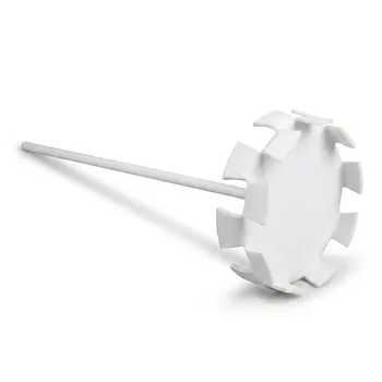
- Customizable PTFE Scrapers and Shovels for Demanding Applications
People Also Ask
- What is the operational temperature range for PTFE laboratoryware? Mastering Thermal Limits from -200°C to +260°C
- What material is used to mold PTFE labware? The Critical Role of Pure PTFE Resin
- What are the primary chemical resistance properties of PTFE laboratory apparatus? Unmatched Purity and Inertness
- What are the primary fabrication methods for PTFE laboratory apparatus? Expert Insights into Fluoropolymer Engineering
- What types of finished products are made from PTFE? Seals, Bearings, Labware & More