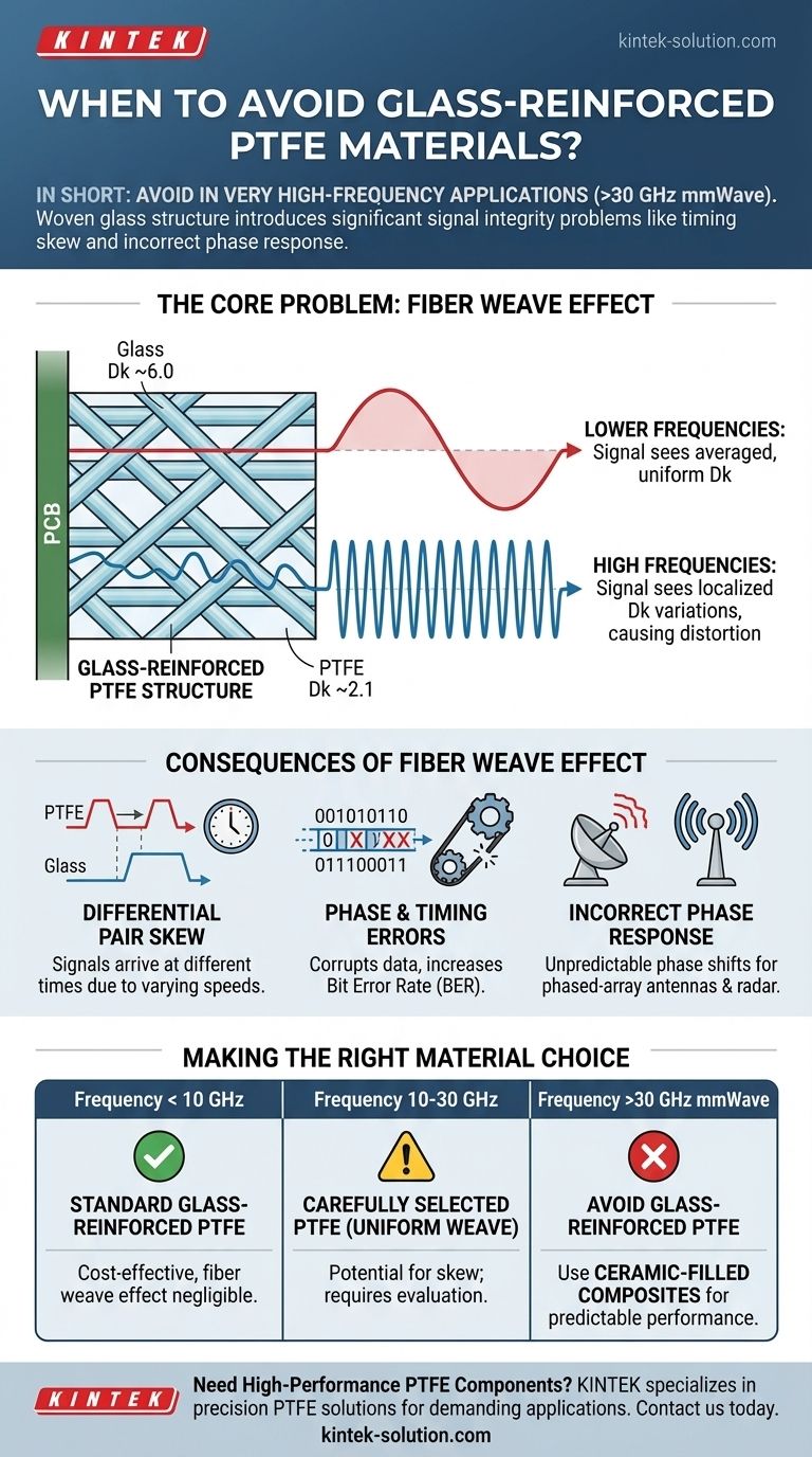
In short, glass-reinforced PTFE materials should be avoided in very high-frequency applications, particularly those operating in the millimeter-wave (mmWave) range above 30 GHz. At these frequencies, the woven glass structure, which provides mechanical stability, introduces significant signal integrity problems like timing skew and incorrect phase response that can cripple a circuit's performance.
The core issue is the "fiber weave effect." The woven glass and the surrounding PTFE have different electrical properties. At lower frequencies, this inconsistency is averaged out, but at the extremely short wavelengths of mmWave signals, it creates an unpredictable and non-uniform electrical environment, distorting the signal.
The Core Problem: The Fiber Weave Effect
To understand when to avoid this material, you must first understand its fundamental structure and its interaction with high-frequency signals.
What is Glass-Reinforced PTFE?
This material is a composite. It combines Polytetrafluoroethylene (PTFE), a plastic known for its excellent low-loss electrical properties, with a woven fabric of glass fibers.
The PTFE provides the electrical performance, while the glass weave adds crucial rigidity and dimensional stability, making it possible to manufacture large, reliable printed circuit boards (PCBs).
Understanding the Dielectric Constant (Dk)
The dielectric constant (Dk) is the most critical property for high-frequency circuit materials. It dictates the speed at which a signal travels through the material.
For high-speed digital and RF signals, having a consistent and predictable Dk across the entire board is non-negotiable.
How the Weave Creates Inconsistency
The problem arises because the two components—PTFE and glass—have very different dielectric constants.
PTFE has a Dk of approximately 2.1, while the glass fibers have a Dk closer to 6.0. This creates a microscopic landscape of varying Dk values across the PCB, corresponding to the pattern of the glass weave.
The Impact at High Frequencies
At lower frequencies (e.g., below 10 GHz), the signal's wavelength is very long compared to the size of the glass weave pattern. The signal effectively "sees" an averaged, uniform Dk and travels predictably.
However, as frequency increases into the mmWave range, the signal's wavelength becomes much shorter—short enough to be on the same scale as the weave pattern itself. The signal no longer sees an average; it experiences the localized pockets of high and low Dk, leading to the fiber weave effect.
The Consequences of the Fiber Weave Effect
When a signal encounters these unpredictable Dk variations, the results are detrimental to circuit performance.
Differential Pair Skew
This is the most common manifestation of the problem. Differential pairs are two traces that carry equal and opposite signals and must remain perfectly synchronized.
If one trace in the pair happens to run over a glass-fiber bundle (high Dk) and the other runs over a PTFE-rich resin pocket (low Dk), their signals will travel at different speeds. The difference in their arrival time at the receiver is called skew.
Phase and Timing Errors
This timing skew corrupts the data. In digital systems, it can cause the receiver to misread the data, leading to a high bit error rate (BER). The two signals no longer cancel out noise effectively, ruining the primary benefit of differential signaling.
Incorrect Phase Response
For analog mmWave systems like phased-array antennas, radar, or communication links, predictable phase is everything.
The random phase shifts introduced by the fiber weave effect make it impossible to maintain the precise phase control needed for these applications to function correctly. The performance becomes unpredictable and unreliable.
Making the Right Material Choice
Selecting the correct circuit board material is a critical design decision that depends entirely on your operating frequency and performance requirements.
- If your primary focus is cost-effective performance below 10 GHz: Standard glass-reinforced PTFE is often an excellent and reliable choice, as the fiber weave effect is negligible.
- If your primary focus is high-speed digital or RF circuits between 10-30 GHz: You must carefully evaluate the material, potentially opting for one with a flatter, more uniform glass weave to mitigate skew.
- If your primary focus is mmWave applications (above 30 GHz): You should actively avoid standard glass-reinforced PTFE and select a more homogeneous substrate, such as a ceramic-filled composite, to ensure predictable performance.
Ultimately, matching your material's properties to your signal's frequency is essential for successful high-performance design.
Summary Table:
| Application Frequency | Material Recommendation | Key Consideration |
|---|---|---|
| Below 10 GHz | Standard Glass-Reinforced PTFE | Cost-effective, fiber weave effect is negligible |
| 10-30 GHz | Carefully Selected PTFE with Uniform Weave | Potential for skew requires evaluation |
| Above 30 GHz (mmWave) | Avoid Glass-Reinforced PTFE; Use Ceramic-Filled Composites | Fiber weave effect causes unacceptable signal distortion |
Need High-Performance PTFE Components for Demanding Applications?
KINTEK specializes in manufacturing precision PTFE components (seals, liners, labware, etc.) for semiconductor, medical, laboratory, and industrial applications. We understand the critical material properties required for high-frequency performance and can help you select or fabricate the right solution.
Our custom fabrication services ensure:
- Material Expertise: We work with various PTFE formulations to meet your specific electrical and mechanical requirements
- Precision Production: Tight tolerances and consistent quality for reliable performance
- Prototype to High-Volume Support: From initial concept to full-scale production
Contact us today to discuss your project requirements and discover how our PTFE expertise can enhance your application's performance and reliability.
Visual Guide
Related Products
- Custom PTFE Teflon Parts Manufacturer Conductive Glass Substrate Cleaning Rack
- Custom Machined Molded PTFE Teflon Parts Manufacturer for Laboratory ITO FTO Conductive Glass Cleaning Flower Basket
- Custom Graphite Filled PTFE Rods for Advanced Industrial Applications
- Corrosion Resistant PTFE Small Reagent Bottle Non Stick Biopharmaceutical Sample Storage Vessel Easy Clean Teflon Container
- High Performance Customizable PTFE Reaction Vessel and Corrosion Resistant Polytetrafluoroethylene Flask for Chemical Laboratory Use
People Also Ask
- What are the advantages and disadvantages of glass-filled PTFE? A Guide to Enhanced Performance & Trade-offs
- What are the advantages of using glass as a filler in PTFE? Enhance Strength and Wear Resistance
- What are the properties of glass-filled PTFE? Enhanced Strength & Wear Resistance for Demanding Applications
- What type of glass is used in glass-filled PTFE? The Definitive Answer for Superior Performance
- How does glass-filled PTFE differ from pure PTFE? A Guide to Enhanced Mechanical Performance