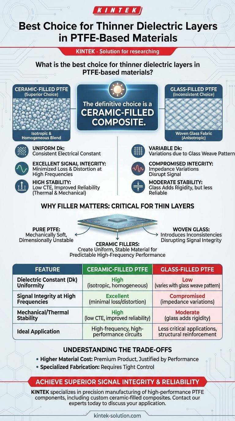
For applications requiring thin dielectric layers in PTFE-based materials, the definitive choice is a ceramic-filled composite. This specific blend provides the necessary electrical consistency and mechanical stability that pure or glass-filled PTFE cannot offer at reduced thicknesses, making it essential for high-frequency and high-performance circuits.
The core issue with thin dielectrics is not just the PTFE itself, but the filler material used to strengthen it. Ceramic fillers create a uniform, stable material ideal for predictable high-frequency performance, while other fillers like woven glass can introduce inconsistencies that disrupt signal integrity.
Why Filler Material is Critical for Thin PTFE Layers
Polytetrafluoroethylene (PTFE) is renowned for its excellent electrical properties, particularly its very low dissipation factor (loss). However, pure PTFE is mechanically soft and dimensionally unstable, especially when subjected to the temperature changes common in circuit board fabrication and operation.
The Role of Fillers
To counteract these mechanical weaknesses, fillers are blended into the PTFE matrix. These additives enhance properties like rigidity, thermal conductivity, and control over the coefficient of thermal expansion (CTE).
Introducing Ceramic Fillers
Ceramic fillers consist of microscopic particles evenly distributed throughout the PTFE. This composition creates an isotropic and homogeneous dielectric material.
This uniformity ensures the dielectric constant (Dk) is consistent across the entire circuit board, which is a non-negotiable requirement for controlled impedance transmission lines in high-frequency designs.
Superior Electrical Performance
The primary advantage of ceramic-filled PTFE is its electrical stability. The material exhibits a low and stable dissipation factor (Df) and a consistent Dk, minimizing signal loss and distortion as frequencies increase into the microwave and millimeter-wave spectrums.
Ceramic-Filled vs. Glass-Filled PTFE: A Direct Comparison
While glass is a common filler for PTFE, it presents significant challenges for high-performance, thin-layer applications, making ceramic a far superior choice.
The Problem with Woven Glass
Many PTFE laminates are reinforced with a woven glass fabric. While this adds rigidity, the weave pattern creates localized variations in the Dk value. A signal trace may pass over a glass knuckle in one area and a resin-rich pocket in another, causing micro-variations in impedance that degrade signal integrity.
The Advantage of Ceramic Homogeneity
Ceramic-filled composites solve this problem. The random and uniform distribution of ceramic particles eliminates the Dk variations caused by a glass weave. This ensures that a 50-ohm transmission line is truly 50 ohms along its entire length, which is critical for sensitive applications.
Mechanical and Thermal Stability
Ceramic fillers also help lower the material's CTE, bringing it closer to that of copper. This reduces stress on plated through-holes and vias during thermal cycling, dramatically improving the long-term reliability of the finished circuit board.
Understanding the Trade-offs
Choosing a specialized material like ceramic-filled PTFE involves acknowledging its specific context within the broader landscape of circuit board materials.
Higher Material Cost
Ceramic-filled PTFE laminates are a premium product. Their cost is significantly higher than standard materials like FR-4 and often higher than glass-reinforced PTFE options. This investment is justified by the performance gains in demanding applications.
Fabrication and Processing
Fabricating circuits on these advanced materials requires specialized knowledge and equipment. The processes for drilling, plating, and etching must be tightly controlled to achieve the desired results and maintain the material's inherent performance advantages.
Making the Right Choice for Your Application
Your final decision should be guided by the performance requirements of your design.
- If your primary focus is high-frequency signal integrity and reliability: Ceramic-filled PTFE is the only suitable choice for thin dielectric layers, as its material uniformity guarantees predictable performance.
- If your primary focus is structural reinforcement for less critical applications: A glass-filled PTFE may be sufficient, but you must accept the inherent risk of electrical inconsistencies.
Ultimately, choosing the right filler is the key to transforming PTFE from a simple low-loss polymer into a high-stability substrate for your most demanding designs.
Summary Table:
| Feature | Ceramic-Filled PTFE | Glass-Filled PTFE |
|---|---|---|
| Dielectric Constant (Dk) Uniformity | High (isotropic, homogeneous) | Low (varies with glass weave pattern) |
| Signal Integrity at High Frequencies | Excellent (minimal loss/distortion) | Compromised (impedance variations) |
| Mechanical/Thermal Stability | High (low CTE, improved reliability) | Moderate (glass adds rigidity) |
| Ideal Application | High-frequency, high-performance circuits | Less critical applications requiring structural reinforcement |
Ready to achieve superior signal integrity and reliability in your high-frequency designs?
At KINTEK, we specialize in the precision manufacturing of high-performance PTFE components, including custom ceramic-filled composites tailored for the semiconductor, medical, and laboratory industries. Our expertise ensures your thin dielectric layers deliver consistent electrical performance and mechanical stability.
Let us help you transform your most demanding designs with materials that guarantee predictable results. Contact our experts today to discuss your specific application and request a quote for custom prototypes or production orders.
Visual Guide
Related Products
- Custom Graphite Filled PTFE Rods for Advanced Industrial Applications
- Custom PTFE Teflon Balls for Advanced Industrial Applications
- Custom PTFE Petri Dishes Corrosion Resistant High Purity Low Background Labware
- Custom PTFE Parts Manufacturer for Teflon Containers and Components
- Custom Machined PTFE Conical Sample Cell Corrosion Resistant Triangular Fluoropolymer Container for Trace Analysis
People Also Ask
- What are PTFE rods and how are they manufactured? A Guide to Their Properties and Production
- What are the benefits of graphite-filled PTFE? Superior Self-Lubrication for Demanding Seals & Bearings
- What are the advantages of Polytetrafluoroethylene (PTFE) with Graphite Fill? Enhance Wear and Friction Performance
- How is graphite filler typically used in PTFE? Enhance Wear Resistance & Self-Lubrication
- What are the characteristics of graphite filled PTFE? Enhance Wear Resistance & Self-Lubrication