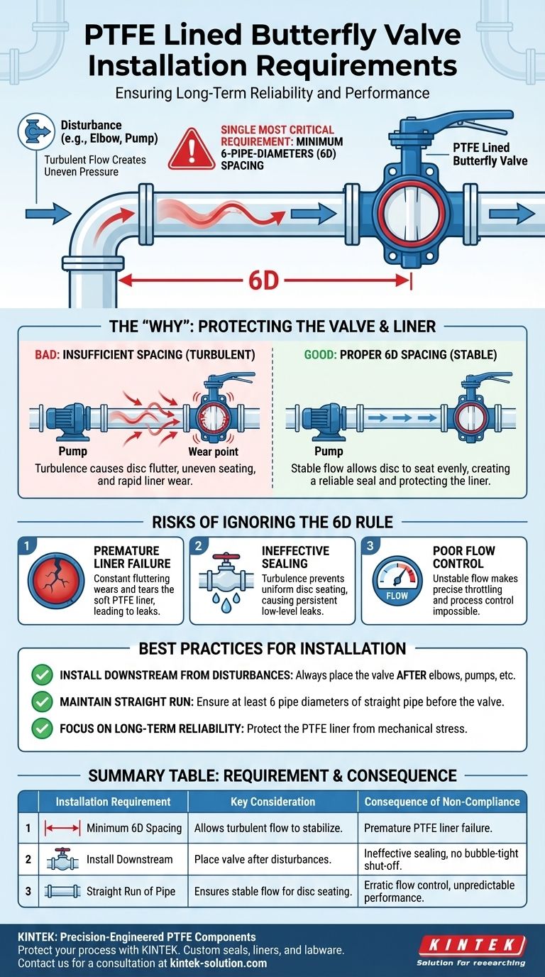
The single most critical installation requirement for PTFE lined butterfly valves is their spacing within the pipeline. To ensure proper function and prevent premature failure, these valves must be installed at least six pipe diameters away from any other line elements, such as elbows, pumps, or other valves that can create flow disturbances.
The core principle behind this rule is to protect the valve's sensitive PTFE liner and ensure a reliable seal. Installing the valve in a straight run of pipe guarantees a stable, non-turbulent flow, which is essential for the disc to seat correctly and prevent damage.
The "Why" Behind the 6-Diameter Rule
The mandate for placing a PTFE lined butterfly valve at least six pipe diameters away from disturbances is not arbitrary. It is rooted in fluid dynamics and the mechanical nature of the valve itself.
Understanding Flow Profile
A fluid moving through a straight pipe develops a stable, predictable flow profile. Bends, pumps, and other fittings disrupt this stability, creating turbulence, swirls, and eddies.
This turbulence does not immediately dissipate. It continues for a significant distance downstream, which is why a clear, straight run of pipe is required to allow the flow to "settle" before it reaches the valve.
How Turbulence Affects the Valve
A butterfly valve operates with a disc that remains in the flow stream. When turbulent flow hits this disc, it creates uneven pressure distribution.
This can cause the disc to flutter or vibrate, especially when in a partially open (throttling) position. This instability directly compromises the valve's performance and structural integrity.
Protecting the Critical PTFE Liner
The primary reason for selecting a PTFE lined valve is for its superior chemical resistance in corrosive applications. The liner is the key component, but it is also the most vulnerable to mechanical stress.
Turbulence causes the disc to seat unevenly against the soft PTFE liner. This can lead to localized high-pressure points, scuffing, and tearing of the liner, ultimately causing the valve to leak and fail. Proper spacing prevents this destructive wear.
Understanding the Trade-offs and Installation Risks
Ignoring the spacing requirement fundamentally undermines the reason for choosing a high-performance lined valve in the first place. The consequences are predictable and costly.
Risk 1: Premature Liner Failure
The most common failure mode from improper installation is damage to the liner. Constant fluttering of the disc against the liner will cause it to wear, tear, or even delaminate from the valve body, leading to a catastrophic leak of aggressive process media.
Risk 2: Ineffective Sealing
A butterfly valve requires a uniform, 360-degree seal between the disc edge and the liner. If turbulent flow prevents the disc from seating correctly, the valve will not provide a bubble-tight shut-off. This can result in persistent, low-level leaks that compromise process control and safety.
Risk 3: Poor Flow Control
In applications where the valve is used for throttling or regulating flow, turbulence can make its performance erratic. The unstable flow profile prevents a predictable relationship between the disc position and the flow rate, making precise process control impossible.
Making the Right Choice for Your Installation
Proper installation is not a guideline but a requirement for performance. Adhering to the spacing rule is the single most important factor in achieving the designed service life and reliability of the valve.
- If your primary focus is long-term reliability in corrosive service: You must enforce the 6-diameter spacing rule to protect the PTFE liner from the mechanical stress of turbulent flow.
- If your primary focus is guaranteed bubble-tight shut-off: Ensure the valve is installed in a sufficient straight run to allow the disc to seat evenly and create a perfect seal every time.
- If you are installing near disruptive elements like pumps or elbows: Always position the valve downstream from the disruption, never before it, and maintain the minimum six-diameter distance to allow the flow to stabilize.
Following these engineering best practices ensures you are protecting your process, your personnel, and your investment.
Summary Table:
| Installation Requirement | Key Consideration | Consequence of Non-Compliance |
|---|---|---|
| Minimum 6-Pipe-Diameter Spacing | Allows turbulent flow to stabilize before reaching the valve. | Premature PTFE liner failure due to disc flutter and uneven wear. |
| Install Downstream from Disturbances | Place valve after elbows, pumps, or other valves. | Ineffective sealing and inability to achieve bubble-tight shut-off. |
| Straight Run of Pipe | Ensures stable, non-turbulent flow for proper disc seating. | Erratic flow control and unpredictable valve performance during throttling. |
Protect your critical processes and investment with precision-engineered PTFE components from KINTEK.
Proper installation is key to performance, but it starts with a high-quality valve. KINTEK specializes in manufacturing custom PTFE seals, liners, labware, and components for the semiconductor, medical, laboratory, and industrial sectors. We ensure precision production from prototypes to high-volume orders, delivering the chemical resistance and reliability your application demands.
Let our experts help you select the right component for your system. Contact KINTEK today for a consultation.
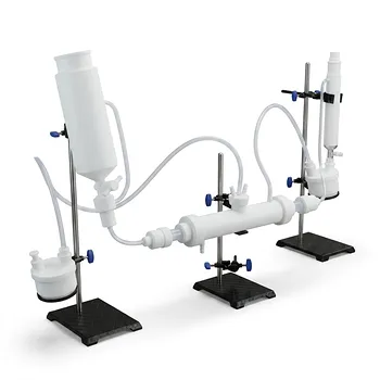
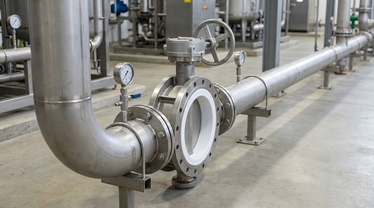
Visual Guide
Related Products
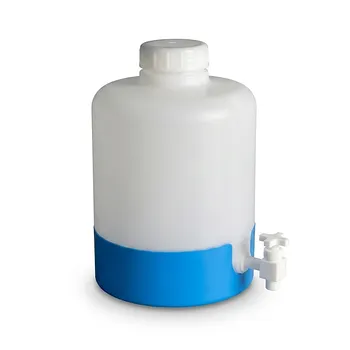
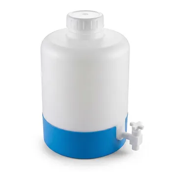
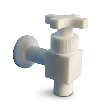
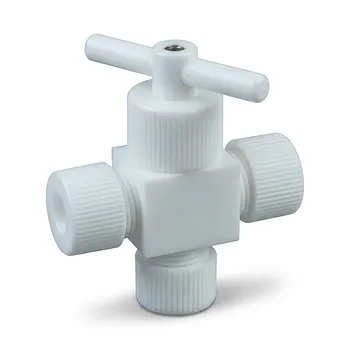
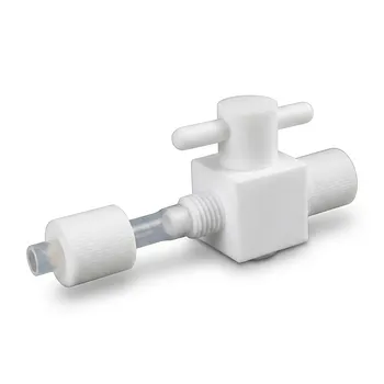
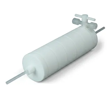
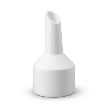
- High Corrosion Resistant PTFE Faucet Polytetrafluoroethylene Valve for Chemical Storage Drums and Fluid Transfer Systems Customizable Industrial Grade
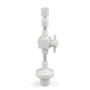
- High Purity PFA PTFE Flare Stop Valves Customizable 2-Way 3-Way Reducing Fluoropolymer Fluid Control Solutions
- High Purity PTFE Faucet Corrosion Resistant Polytetrafluoroethylene Drum Valve Customizable Lab Chemical Fluid Control
- Corrosion Resistant PTFE Polytetrafluoroethylene Valve and Customizable Laboratory Fluid Dispensing Faucet for Aggressive Chemical Handling in Industrial Storage Tanks and Plastic Drums
- Custom PTFE Valve 2-Way 3-Way Corrosion Resistant Low Background Virgin Fluoropolymer Industrial Fluid Control
People Also Ask
- What specific advantages do PTFE valves offer? Unmatched Corrosion Resistance for Industrial Chemical Handling
- What technical principles govern the sealing performance of PTFE-based valve components? Achieve Near-Zero Leakage
- What are the key properties of PTFE valves? Ensure Purity, Safety, and Reliability in Demanding Processes
- What support is available for selecting the right PTFE valve design and size? Get Expert Guidance for Your Application
- Why are PTFE valves used in food and beverage processing equipment? Ensure Purity, Safety, and Easy Cleaning