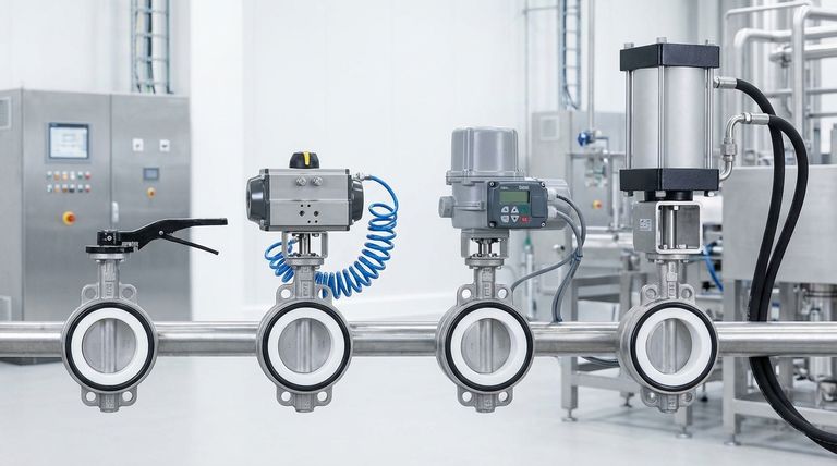
PTFE butterfly valves are operated through four primary mechanisms. These include simple manual operators like levers and gears for direct control, as well as automated systems using pneumatic, electric, or hydraulic actuators, each engineered for specific performance, speed, and precision requirements.
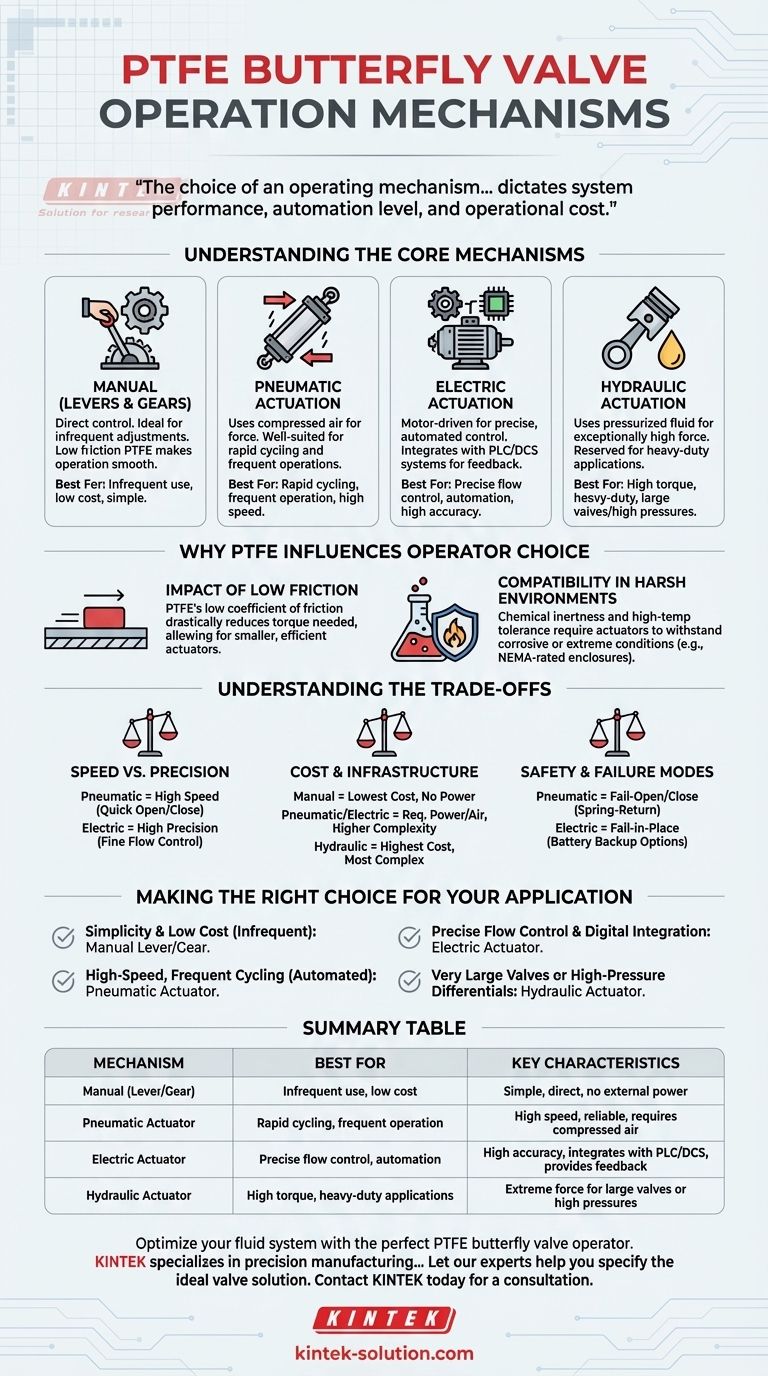
The choice of an operating mechanism for a PTFE butterfly valve is not merely about opening and closing it; it is a critical decision that dictates system performance, automation level, and operational cost. Understanding your application's need for speed, precision, and force is the key to selecting the right operator.
Understanding the Core Mechanisms
Each operation method offers distinct advantages suited to different industrial environments and control philosophies. The selection process involves evaluating the frequency of use, the need for automation, and the available power sources.
Manual Operation (Levers & Gears)
Manual operators are the most direct and simplest method for controlling a PTFE butterfly valve. They typically consist of a lever (for smaller valves) or a handwheel with a gearbox (for larger valves).
This method is ideal for applications where the valve is adjusted infrequently. The inherent low-friction properties of PTFE significantly reduce the torque needed to turn the valve, making manual operation smooth and reliable.
Pneumatic Actuation
Pneumatic actuators use compressed air to generate the force required to open and close the valve. They are well-suited for applications demanding rapid cycling and frequent operations.
These actuators are known for their high reliability, speed, and relatively simple design. They are a common choice in process automation where a compressed air supply is readily available.
Electric Actuation
Electric actuators use a motor to drive a gear train, providing the torque to operate the valve. Their primary advantage lies in precise, automated control.
They can be easily integrated with PLC or DCS systems, allowing for exact positioning for metered flow and providing valuable feedback on the valve's status. This makes them ideal for complex, automated processes requiring high accuracy.
Hydraulic Actuation
Hydraulic actuators use pressurized fluid (typically oil) to generate motion. They are reserved for heavy-duty applications that demand exceptionally high force (torque).
This mechanism is necessary for operating very large valves or for systems with extreme pressure differentials where pneumatic or electric actuators would be insufficient.
Why PTFE Influences Operator Choice
The material properties of Polytetrafluoroethylene (PTFE) are not just relevant to the valve's sealing and chemical resistance; they directly impact the requirements of the operating mechanism itself.
The Impact of Low Friction
PTFE has one of the lowest coefficients of friction of any solid material. This characteristic is a significant advantage in butterfly valves.
The low friction between the PTFE seat and the disc dramatically reduces the torque needed to operate the valve. This allows for the use of smaller, less expensive, and more energy-efficient actuators compared to valves with higher-friction seating materials.
Compatibility in Harsh Environments
The chemical inertness and high-temperature tolerance of PTFE mean these valves are often placed in corrosive or extreme temperature environments.
The actuator chosen must also be able to withstand these conditions. For example, a pneumatic actuator might be preferred in an explosive atmosphere for its intrinsic safety, or an electric actuator may require a special NEMA-rated enclosure to protect it from corrosive fumes.
Understanding the Trade-offs
No single mechanism is universally superior. The optimal choice always involves balancing performance, complexity, and cost for your specific context.
Speed vs. Precision
Pneumatic actuators offer the highest cycling speed, making them perfect for quick open/close applications. However, they are generally less precise for throttling or modulating flow.
Electric actuators, while typically slower, provide unparalleled precision, allowing for fine adjustments to the valve position for exact flow control.
Cost and Infrastructure
Manual operators have the lowest initial cost and require no external power infrastructure.
Pneumatic systems require a source of clean, dry compressed air, which adds to system complexity. Electric actuators require a power supply and control wiring, while hydraulic systems are the most complex and expensive, needing a hydraulic power unit, lines, and fluid.
Safety and Failure Modes
A key consideration is how the valve should behave in a power failure. Pneumatic actuators can be easily configured to be "fail-open" or "fail-close" using spring-return models.
Electric actuators typically "fail-in-place," meaning they remain in their last position when power is lost, though models with battery backups are available.
Making the Right Choice for Your Application
To select the most effective operator, align the mechanism's strengths with your primary operational goal.
- If your primary focus is simplicity and low cost for infrequent adjustments: A manual lever or gear operator is the most direct and economical solution.
- If your primary focus is high-speed, frequent cycling in an automated system: A pneumatic actuator provides the necessary rapid response and durability.
- If your primary focus is precise flow control and integration with a digital system: An electric actuator offers superior accuracy and feedback capabilities for sophisticated automation.
- If your primary focus is operating very large valves or overcoming high-pressure differentials: A hydraulic actuator is the only choice that can reliably generate the required high torque.
Ultimately, selecting the correct operator transforms the valve from a simple component into an optimized and reliable part of your process control strategy.
Summary Table:
| Mechanism | Best For | Key Characteristics |
|---|---|---|
| Manual (Lever/Gear) | Infrequent use, low cost | Simple, direct control, no external power needed |
| Pneumatic Actuator | Rapid cycling, frequent operation | High speed, reliable, requires compressed air |
| Electric Actuator | Precise flow control, automation | High accuracy, integrates with PLC/DCS, provides feedback |
| Hydraulic Actuator | High torque, heavy-duty applications | Extreme force for large valves or high pressures |
Optimize your fluid system with the perfect PTFE butterfly valve operator.
Selecting the right operating mechanism is critical for the performance, efficiency, and reliability of your valves in demanding semiconductor, medical, laboratory, and industrial applications. KINTEK specializes in the precision manufacturing of high-performance PTFE components, including custom butterfly valves and seals.
We understand the nuances of actuator selection and can guide you from prototype to high-volume production to ensure optimal integration and performance.
Let our experts help you specify the ideal valve solution. Contact KINTEK today for a consultation.
Visual Guide
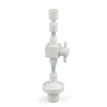
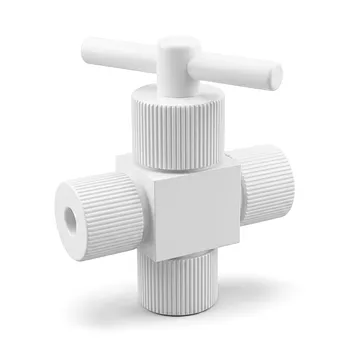
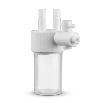
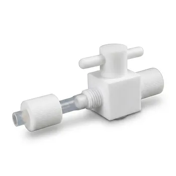
Related Products
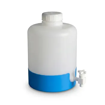
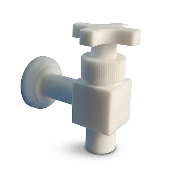
- High Corrosion Resistant PTFE Faucet Polytetrafluoroethylene Valve for Chemical Storage Drums and Fluid Transfer Systems Customizable Industrial Grade
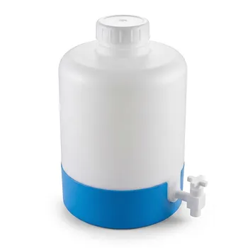
- High Purity PTFE Faucet Corrosion Resistant Polytetrafluoroethylene Drum Valve Customizable Lab Chemical Fluid Control
- Corrosion Resistant PTFE Polytetrafluoroethylene Valve and Customizable Laboratory Fluid Dispensing Faucet for Aggressive Chemical Handling in Industrial Storage Tanks and Plastic Drums
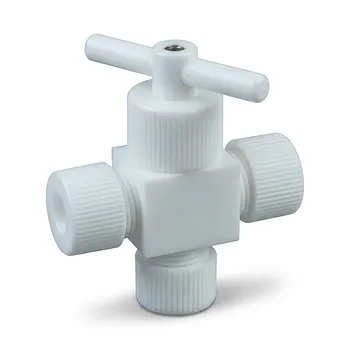
- Custom PTFE Valve 2-Way 3-Way Corrosion Resistant Low Background Virgin Fluoropolymer Industrial Fluid Control
- High Purity PFA PTFE Flare Stop Valves Customizable 2-Way 3-Way Reducing Fluoropolymer Fluid Control Solutions
People Also Ask
- What are the benefits of using PTFE valves in the food processing industry? Ensure Safety, Purity, and Efficiency
- What industries commonly use PTFE valves and components? Essential for Chemical & Purity Applications
- What is the typical operating temperature and pressure range for PTFE valves? Key Specs for Optimal Performance
- What are the key properties of PTFE valves? Ensure Purity, Safety, and Reliability in Demanding Processes
- Why are PTFE valves used in food and beverage processing equipment? Ensure Purity, Safety, and Easy Cleaning