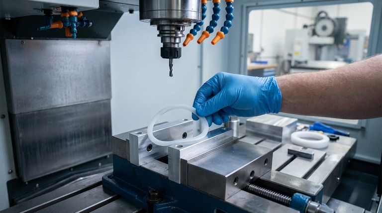
To properly clamp thin-wall PTFE components, you must use a method that distributes pressure evenly across a large surface area. The best options are custom-fit soft jaws or precision vacuum fixtures. The goal is to apply a clamping force significantly below PTFE's yield strength of 20–30 MPa to prevent any deformation while ensuring the part remains secure.
The key to machining thin-wall PTFE is recognizing that successful workholding is only one part of the equation. You must adopt a holistic strategy that manages the material's inherent softness, low friction, and high thermal expansion to prevent distortion from clamping pressure and cutting forces alike.
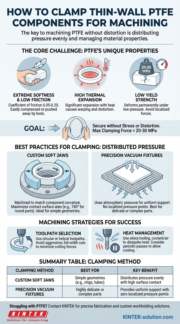
The Core Challenge: PTFE's Unique Properties
Understanding Polytetrafluoroethylene (PTFE) is the first step to machining it successfully. Its properties make it highly desirable for many applications but also create specific challenges during fabrication.
Extreme Softness and Low Friction
PTFE is an exceptionally soft and slippery material, with a coefficient of friction between 0.05 and 0.20. This means it can easily be compressed, deformed, or pushed away by cutting tools if not properly supported.
High Thermal Expansion
The material expands and contracts significantly with temperature changes. Heat generated during machining can easily cause thin walls to warp or distort, ruining dimensional accuracy.
Low Yield Strength
Yield strength is the point at which a material begins to deform permanently. PTFE's low yield strength (20–30 MPa) means that even moderate, localized clamping pressure from standard hard jaws will crush it.
Best Practices for Workholding and Clamping
The primary goal of any clamping strategy for PTFE is to secure the workpiece without introducing any stress or distortion. This requires moving away from high-pressure, localized clamping.
The Principle of Distributed Pressure
Instead of pinching the material, your workholding should cradle it. The force must be spread across the largest possible surface area to keep the pressure at any single point to an absolute minimum.
Using Soft Jaws
Soft jaws, typically made from aluminum, are the most common solution. They should be machined to precisely match the curvature of the component, ensuring 180-degree contact for round parts. This maximizes surface area and distributes the load evenly.
Employing Vacuum Fixtures
For the most delicate or complex thin-wall components, a precision vacuum fixture is the superior choice. This method uses atmospheric pressure to hold the part against a perfectly flat or custom-shaped surface, providing completely uniform support with no localized pressure points.
Beyond Clamping: Machining Strategies for Success
Effective clamping is critical, but it will fail if the machining process itself introduces excessive stress. Your cutting strategy must be designed to accommodate the material's delicate nature.
Toolpath Selection
Avoid aggressive, full-width cuts that engage the entire tool diameter. Instead, use circular or helical toolpaths to peel material away gently. This approach minimizes cutting forces and reduces vibration on thin sections.
Heat Management is Critical
You must prevent heat buildup at all costs. Use sharp tooling to reduce friction, apply coolant or compressed air to dissipate heat, and consider periodic pauses in the toolpath to allow the material to cool and stabilize.
Understanding the Trade-offs
Machining thin-wall PTFE involves a delicate balance. Pushing too hard in any one area will lead to failure.
Over-clamping vs. Part Slippage
The central conflict is securing the part tightly enough that it doesn't move while being so gentle that you don't deform it. This requires careful feel and fixtures that offer broad support rather than brute force.
Machining Speed vs. Thermal Stability
Aggressive feeds and speeds may seem efficient, but they generate excessive heat that will cause the part to warp. A slower, more deliberate approach is necessary to maintain dimensional accuracy in thin sections.
Fixture Complexity vs. Part Geometry
A simple ring might be machined perfectly with well-made soft jaws. However, a more complex or thinner part may be impossible to hold without a custom-machined vacuum fixture, which adds significant time and cost to the setup.
Making the Right Choice for Your Goal
Your workholding strategy should be dictated by the part's geometry and your primary goal.
- If your primary focus is preventing deformation on simple shapes: Custom-bored soft jaws that maximize surface contact are the most practical and effective starting point.
- If your primary focus is machining highly delicate or complex parts: A precision vacuum fixture is the most reliable method for providing uniform, stress-free support.
- If your primary focus is achieving overall process reliability: Combine your chosen clamping method with low-stress toolpaths and active thermal management to ensure success.
Ultimately, mastering thin-wall PTFE machining comes from treating the material with finesse, not force.
Summary Table:
| Clamping Method | Best For | Key Benefit |
|---|---|---|
| Custom Soft Jaws | Simple geometries (e.g., rings, tubes) | Distributes pressure evenly with high surface contact |
| Precision Vacuum Fixtures | Highly delicate or complex parts | Provides uniform support with zero localized pressure points |
Struggling to machine thin-wall PTFE without distortion? KINTEK specializes in the precise fabrication of PTFE components for the semiconductor, medical, and laboratory industries. Our expertise in custom workholding and low-stress machining ensures your delicate parts are held securely and machined to exact specifications, from prototypes to high-volume orders.
Contact KINTEK today to discuss your project and get a quote.
Visual Guide
Related Products
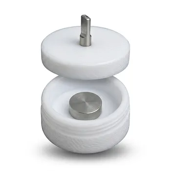
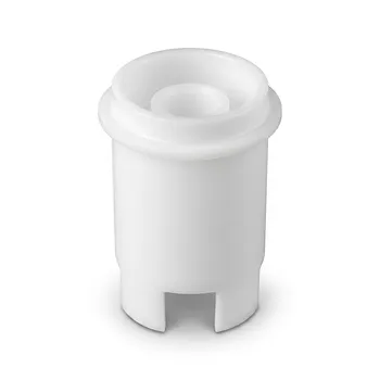
- Acid Resistant PTFE Button Cell Battery Test Fixture Customizable Machining High Purity Electrochemical Testing Clamp
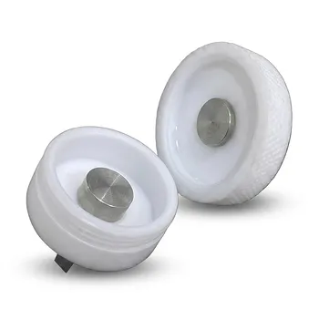
- Corrosion Resistant PTFE Coin Cell Battery Testing Clamps and Acid Proof Custom Fluoropolymer Battery Fixtures
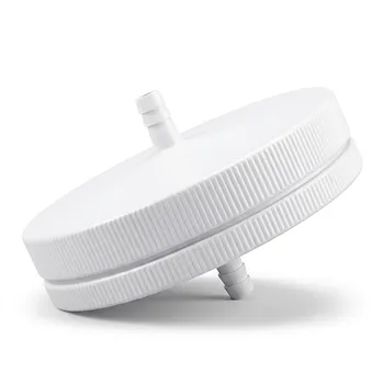
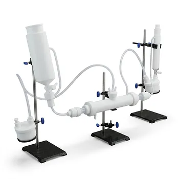
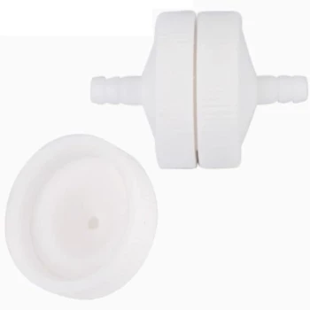
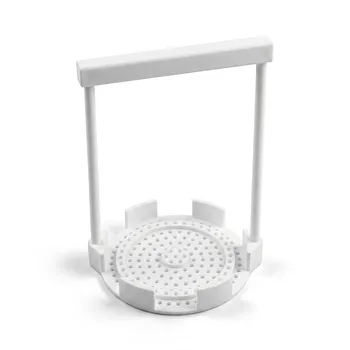
- PTFE Filter Membrane Holder for Hydrogen Chloride and Water Filtration 90mm Environmental Sampling Clamp Customizable
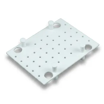
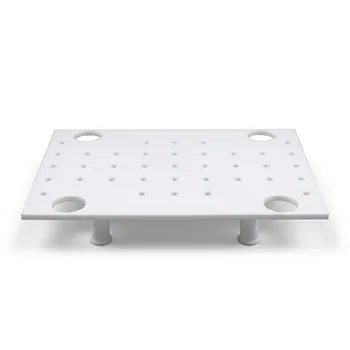
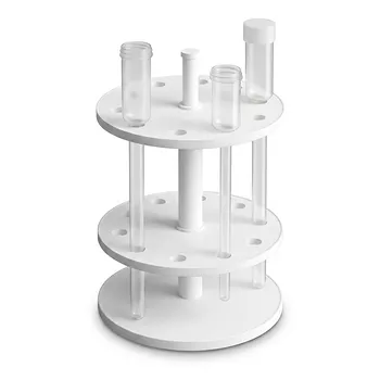
- Customizable PTFE Heat Insulation Plate High Temperature Corrosion Resistant Laboratory Support Layered Multi Tier Stand
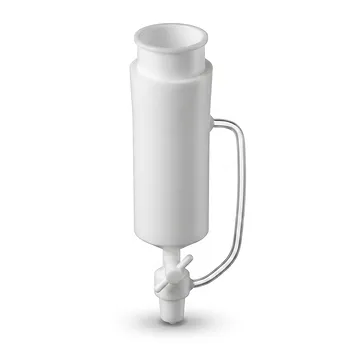
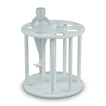
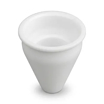
- Custom PTFE Constant Pressure Separatory Funnel Corrosion Resistant Low Background Labware for PFA Flasks
People Also Ask
- What are the electrical insulation specifications of the PTFE material used in battery clamps? Ensure Precision & Safety
- How do PTFE battery clamps perform in specialized systems? Enhance Precision and Durability in Corrosive Environments
- How does the structural design of a PTFE battery clamp minimize electrical noise? Precision Engineering for Clean Data
- In what industrial manufacturing contexts are PTFE battery clamps or fixtures utilized? Optimize Battery Production.
- What are the primary functions and material compositions of PTFE battery clamps? Ensure Precision & Chemical Resistance